CRANE GIRDER DESIGN BS5950
Description
Calculation Reference
Crane Design
BS5950
Structural Design
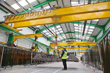
Designing a crane girder according to BS5950 involves numerous steps to ensure that it can safely support the applied loads, including the weight of the crane and the lifted load, the crane movement, and the imposed wind loads.
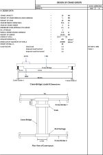
The following are the design parameters you mentioned, which are required to perform the design:
- Crane capacity
- Weight of crane bridge & end carriage
- Weight of crab
- Span between crane rails
- Span of crane girder
- Minimum hook approach to girder
- Number of wheels
- Wheel centres in end carriage
- Weight of girder
- Grade of steel
- Design strength, Py
- Modulus of elasticity of steel, E
- Height of rail, Hr
- Load factor
In the context of BS5950, which is a British Standard for the design of steel structures, the term 'load factor' refers to the factor of safety applied to various loads when carrying out design calculations.
The load factors are used as multipliers on the characteristic (nominal) loads to ensure that the structure is safe under worst-case scenarios, and they account for the uncertainties and variabilities in the loads as well as the material properties.
Typically, different types of loads will have different load factors applied to them, reflecting the degree of uncertainty associated with each load type. For instance:
-
Permanent Loads (also known as Dead Loads): These are the weights of the structural members and any other permanent fixtures attached to them. Since these loads are relatively well known and do not change significantly over time, they typically have a lower load factor. In BS5950, the load factor for dead loads is generally 1.4.
-
Imposed Loads (also known as Live Loads): These are loads that can change over time, such as occupancy loads, equipment loads, and snow loads. These loads are less predictable and can vary significantly, so they have a higher load factor. In BS5950, the load factor for live loads is typically 1.6.
-
Wind Loads: Wind loads can be highly variable and unpredictable. Therefore, they usually have a higher load factor. In BS5950, the load factor for wind loads is typically 1.4.
The load factors are used in load combinations, which represent the different scenarios of load application that the structure must be designed to withstand. Load combinations typically include both the worst-case scenario for a single load type, and scenarios where multiple types of loads are acting simultaneously.
It's important to note that these values may vary depending on the design situation, load duration, and whether the design is for an ultimate limit state (ULS) or a serviceability limit state (SLS).
Once the data is collected, the design steps will typically include the following checks:
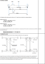
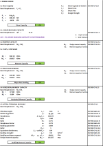
I.1 Shear Capacity This involves checking that the shear force in the girder (due to the crane load and the self-weight of the girder) does not exceed the shear capacity of the section.
I.1.1 Shear Buckling Capacity Shear buckling capacity needs to be checked for slender web sections which might buckle under shear stresses. It's especially important for sections with high web slenderness.
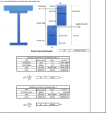
I.2 Moment Capacity This involves checking that the bending moment in the girder (due to the crane load and the self-weight of the girder) does not exceed the moment capacity of the section.
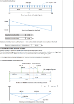
I.3 Major Axis Bending This involves checking the resistance of the girder to major axis bending due to the applied loads.
I.4 Horizontal Moment Capacity This checks the capacity of the girder to resist horizontal bending moments.
I.5 Lateral Torsional Buckling This checks the resistance of the girder to lateral torsional buckling, which is a combination of bending and torsion.
I.6 Combined Vertical & Horizontal Moment Capacity This involves checking the capacity of the girder to resist a combination of vertical and horizontal bending moments.
I.7 Unstiffened Web Bearing Capacity This checks the ability of the web to resist bearing loads from the wheels of the crane without stiffeners.
I.8 Unstiffened Web Buckling Capacity This checks the resistance of the web to buckling under compression, without the use of stiffeners.
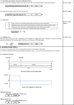
I.9 Vertical Deflection This involves checking the deflection of the girder under vertical loads to ensure that it is within acceptable limits (usually span/500 or span/400 depending on the usage).
I.10 Horizontal Deflection This involves checking the deflection of the girder under horizontal loads to ensure that it is within acceptable limits.
I.11 Local Compression under Wheel This checks the resistance of the girder to localized compression stresses under the crane wheels.
Calculation Preview
Full download access to any calculation is available to users with a paid or awarded subscription (XLC Pro).
Subscriptions are free to contributors to the site, alternatively they can be purchased.
Click here for information on subscriptions.


Thus unable to reset the runway geometry for the configuration entered and thus cannot proceed beyond this point for the analysis. Can you advise or rectify.