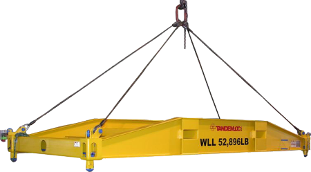
Spreader Bar Lifting Device Calculations and Design
Description
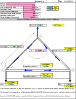
Safe Working Load, SWL
Spreading Length
Safety Factor in Compression
Yield stress of the Beam material
Allowable Tensile Stress
Elastic Modulus of the material
(A) Design for Normal Stress (Direct Compressive Stress) Selecting the Section initially based on this
(B) Design for Elastic Stability - Transverse Buckling [1]
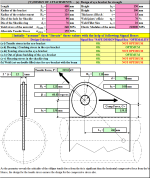
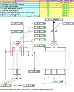
('C) DESIGN OF ATTACHMENTS - (a) Design of eye bracket for strength
(a-i) Design of eye bracket for tensile strength - FAILURE MODE - 1 (allowable tensile stress is governing)
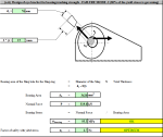
(a-ii) Design of eye bracket for bearing/crushing strength - FAILURE MODE -2 (80% of the yield stress is governing)
(a-iii) Design of eye bracket for tearing strength - FAILURE MODE - 3 (50% of the yield stress is governing)
(a-iv) Design of eye bracket for out-of plane buckling - FAILURE MODE - 4 (as per David T. Ricker [2])
(a-v) Design of shackle ring for shearing strength - FAILURE MODE - 5 (50% of the yield stress is governing)
(b) Design of weld joint of the eye-bracket with the spreader beam for shear strength (50% of the allowable stress is governing)
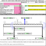
DESIGN OF ADJUSTABLE SPREADER LIFTING BEAM of Standard Profile "HEB Series"
Geometry of Lifting at the each end of the HOLLOW PIPE Spreader Beam, Solved using the equations of Static Equillibrium
(A) STRENGTH DESIGN - Design for FLEXURAL Bending Stress Selecting the Section initially based on this
(B) STIFFNESS DESIGN - Design for DEFLECTION
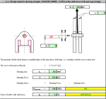
(C) DESIGN OF ATTACHMENTS - (a) Design of adjustable (CG location variations) suspension bracket for strength
(a-i) Design of lugs on the bracket for tensile strength - FAILURE MODE - 1 (allowable tensile stress is governing)
(a-ii) Design of lugs on the bracket for bearing/crushing strength - FAILURE MODE -2 (80% of the yield stress is governing)
(a-iii) Design of lug on the bracket for tearing strength - FAILURE MODE - 3 (50% of the yield stress is governing)
(a-iv) Design of lug on the bracket for out-of plane buckling - FAILURE MODE - 4 (as per David T. Ricker [1])
(a-v) Design of pin for shearing strength - FAILURE MODE - 5 (50% of the yield stress of the pin is governing)
(b) Design of weld joint of the lug with other plates for shear strength (50% of allowable stress is governing)
(c) Design of end plates of the adjustable bracket for tensile strength (allowable tensile stress is governing)
(d) Design of weld joint for the bottom plate of the adjustable bracket for shear strength (50% of allowable tensile stress is governing)
(D) DESIGN OF ATTACHMENTS - (a) Design of adjustable (Span variations) suspension bracket for strength
(a-i) Design of lugs on the bracket for tensile strength - FAILURE MODE - 1 (allowable tensile stress is governing)
(a-ii) Design of lugs on the bracket for bearing/crushing strength - FAILURE MODE -2 (80% of the yield stress is governing)
(a-iii) Design of lug on the bracket for tearing strength - FAILURE MODE - 3 (50% of the yield stress is governing)
(a-iv) Design of lug on the bracket for out-of plane buckling - FAILURE MODE - 4 (as per David T. Ricker [1])
(a-v) Design of pin for shearing strength - FAILURE MODE - 5 (50% of the yield stress of the pin is governing)
(b) Design of weld joint of the lug with other plates for shear strength (50% of allowable stress is governing)
(c) Design of end plates of the adjustable bracket for tensile strength (allowable tensile stress is governing)
(d) Design of weld joint for the top plate of the adjustable bracket for shear strength (allowable tensile stress is governing)
(E) DESIGN OF ATTACHMENTS - (a) Design of fixed suspension bracket for strength
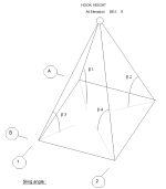
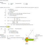
LIFTING ARRANGEMENT AND PADEYE DESIGN
Center of Gravity Calculation
"RIGGING CALCULATION For Inshore Lifting"
Calculation Reference
Lifting Design
Structural Steel
Safe Working Load Design
Calculation Preview
Full download access to any calculation is available to users with a paid or awarded subscription (XLC Pro).
Subscriptions are free to contributors to the site, alternatively they can be purchased.
Click here for information on subscriptions.
John - I'm trying to review your comments now and see where you are referencing by the link you have mentioned. It shouldn't contain any links to an outside file source but I will review and get back to you with a resolution. Thank you for reviewing and catching this.
Good Spreadsheet

