Gravity Pipe Flow - Manning's Equation
Description
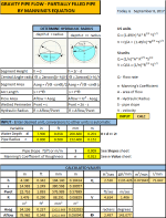
Gravity pipe flow of a partially filled pipe.
Hydraulic radius is calculated and all hydraulic properties of the pipe are calculated in a table.
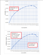
Three charts are provided to highlight maximum and special conditions for hydsraulic radius (R), flow rate (Q) and velocity (V).
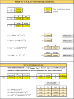
Manning's n, hydraulic radius, slope and velocity can also be calculated for existing conditions.
GRAVITY PIPE FLOW - PARTIALLY FILLED PIPE
BY MANNING'S EQUATION
References:
Gravity Flow in Pipes - The Manning Formula, William C. Dunn PE
Manning Equations, Robert Pitt & Shirley Clark
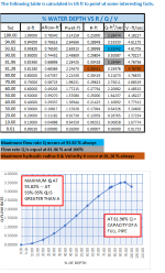
Validation: Worked through book examples & hand calculations. Some variables in manning's equations have interesting properties shown in the table & Charts on the Calcs sheet, providing a method of self validation. Place cursor on dots on the charts to get values.
Calcs Sheet: Determine the hydraulic radius based on water depth in pipe. Input is US or SI; use the units of your choice, the rest are converted automatically. Output is in US & SI units. A Table based on percent of water depth points out some interesting properties of hydraulic radius, flow rate and velocity. Charts show visually the properties of hydraulic radius, flow rate, and velocity plotted against percent of water depth in the pipe.
Find Depth of Flow -- Q, n, S, r Known. Enter n, S and r. Take a guess at d. Keep incrementing or decrementing d until Q = known value. You have found d.
n-Value Sheet: Provides a Table of Manning's coefficient n.
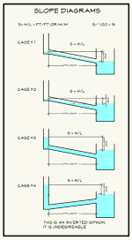
Slopes Sheet: Explains visually how slopes are determined.
n,R,S,V Sheet: Helps to solve for n, R, S, V for existing conditions. Provides calculations to determine pipe diameter with known design requirements of Q, Vallowable, Smin, and n.
Calculation ReferenceGravity Pipe Flow
Piping Calculations
Manning's Equation
Manning's Equation is a widely used empirical formula for calculating the flow of water in open channels and gravity-driven pipes. The equation is named after the Irish engineer Robert Manning, who introduced it in 1889. Manning's Equation is particularly useful for gravity pipe flow because it accounts for the pipe's slope, roughness, and cross-sectional shape, allowing for accurate flow calculations under various conditions.
The Manning's Equation is given by:
Q = (1/n) * A * R^(2/3) * S^(1/2)
where:
- Q is the flow rate (m³/s or ft³/s)
- n is the Manning's roughness coefficient (dimensionless), which depends on the pipe material and surface roughness
- A is the cross-sectional area of flow (m² or ft²)
- R is the hydraulic radius (m or ft), defined as the ratio of the cross-sectional area of flow (A) to the wetted perimeter (P): R = A / P
- S is the slope of the pipe or energy gradient (dimensionless), typically approximated as the ratio of the vertical drop in elevation (h) to the horizontal pipe length (L): S = h / L
To use Manning's Equation for gravity pipe flow calculations, follow these steps:
-
Determine the pipe's cross-sectional area (A) and wetted perimeter (P) based on the pipe's diameter (D) and flow depth (if the pipe is partially full). For a circular pipe running full, A = ?D²/4 and P = ?D.
-
Calculate the hydraulic radius (R) using the formula R = A / P.
-
Estimate the slope of the pipe (S) by measuring the vertical drop in elevation (h) and the horizontal pipe length (L), and then calculating the ratio: S = h / L.
-
Obtain the Manning's roughness coefficient (n) for the pipe material. Typical values range from 0.009 to 0.015 for concrete pipes and 0.012 to 0.035 for corrugated metal pipes. The exact value depends on the material and surface roughness.
-
Plug the values for A, R, S, and n into the Manning's Equation and calculate the flow rate (Q).
Keep in mind that Manning's Equation assumes steady, uniform flow and is best suited for relatively simple pipe systems. For more complex systems or non-steady flow conditions, other methods or computational fluid dynamics (CFD) models may be necessary.
Calculation Preview
Full download access to any calculation is available to users with a paid or awarded subscription (XLC Pro).
Subscriptions are free to contributors to the site, alternatively they can be purchased.
Click here for information on subscriptions.

