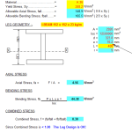
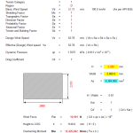
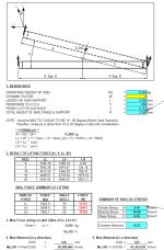
Weight & Bolting_lse.xls
Description
PLEASE NOTE: "Lift Lug calc for Skid" has links with "Weight & Bolting_lse.xls" These may be downloaded separately or together as a zip file.
1 DESIGN DATA
2 DESIGN CALC DESCRIPTION & ASSUMPTION
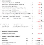
3 WEIGHT AND ANALYSIS SUMMARY
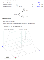
4 CENTRE OF GRAVITY RESULTS FROM STAAD ANALYSIS
5 STAAD OUTPUT : RESULTS AND ANALYSIS SUMMARY
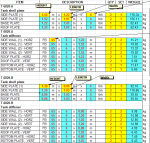
6 WEIGHT CALCULATION
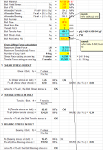
7 LOAD AT BASE CALCULATION
8 LEG DESIGN CALCULATION
9 BASE PLATE DESIGN CALCULATION
10 TRANSPORTATION LOAD CALCULATION
11 WIND LOADING CALCULATION
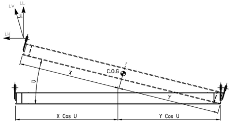
12 CALC OF LIFTING FORCE (SKID)
13 LIFTING LUG DESIGN CALC (SKID)
14 LIFTING SPREADER PIPE SIZING CALC (SKID)
15 SLING & WIRE ROPE CALC @ SPREADER BAR (SKID) - S5 & S6
16 SLING & WIRE ROPE CALC (SKID) - S1 TO S4
17 LIFTING LUG DESIGN CALC (TANK)
18 LIFTING SPREADER PIPE SIZING CALC (TANK)
19 SLING & WIRE ROPE CALC @ SPREADER BAR (TANK) - S5 & S6
20 SLING & WIRE ROPE CALC (TANK) - S1 TO S4
APPENDIX
A1 ALLOWABLE STRESS REFERENCE
DESIGN DATA
Service Tote Tank
Design Pressure ( Max : Full water + 5 kPa / Min : -0.2 kPa )
Design Temperature ( Max : 65 / Min : 0 oC )
Operating Pressure ATM
Operating Temperature Ambient
Capacity 2 m3
Size 1219(L) x 1067(W) x 1524(H)
Material A 240 316L
Design Code API 650 & Roark's Formulas for Stress & Strain
Material A 240 316L
Tank plate thickness 6 mm
Yield Stress, σy 172369 kPa
Max Allowable Stress 115142 kPa
SKID SUPPORT OVERALL DIMENSION
2500 WIDTH (mm)
2800 LENGTH (mm)
7.0 AREA (m2)
EN10025 S275JR STRUCTURAL BEAM MATERIAL
Design Calculation Description :
Design and Lifting Calculations for Chemical Injection System Skid of this project is written in MS-Excel for the purpose of calculating the optimum sizing of lifting gears . Specifically, the design is based on Bending Equation formulas and Standard engineering formulas & AISC Lifting calculations is used to analysed the required dimensional thickness and strength of the lifting lugs
(Skid & its tank) during lifting operation. Bending equations of "Simply supported beam" and "Statically indeterminate beams" are used in calculating required size of the spreader beam section used. The slings and shackle sizes are also selected after selection of lifting lugs for the tanks and skid . STAAD PRO software is used to facilitate analysing skid structural frame strength.
The formula for determining the bending stress in a beam under simple bending is :
σ is the bending stress
M - the moment about the neutral axis
y - the perpendicular distance to the neutral axis
Ix - the second moment of area about the neutral axis x
b - the width of the section being analyzed
h - the depth of the section being analyzed
Weight and Centre of Gravity Calculation Description :
Weight for Chemical Injection System Skid of this project is written in MS-Excel for the purpose of calculating the lifting weight of the Skid. STAAD Output result from post analysis during lifting is able to calculate the Centre Of Gravity (C.O.G) of Skid and its Equipment during lifting operation.
Design Calculation Assumptions :
4. The Bending stress formulas in the calculation are based on the following assumptions:
(4.1) The beams are assumed to be symmetric about the x-y plane
(4.1) All loads must act in the x-y plane.
(4.1) A right handed coordinate system is adopted, with x-axis along the longitudinal axis of the beam.
References :
- Pressure Vessel Handbook (7th Edition) by Henry H. Bedner
- Pressure Vessel Handbook by Eugene F. Megyesy
- AISC (Manual of Steel Construction - Specification for Design, Fabrication and Erection of Structural Steel for Building (9th Edition) ASD.
Calculation Reference
Skid Design
Sling and Rope Design
Lifting Lug Design
Calculation Preview
Full download access to any calculation is available to users with a paid or awarded subscription (XLC Pro).
Subscriptions are free to contributors to the site, alternatively they can be purchased.
Click here for information on subscriptions.

