POLEFDN.xls

Description
'POLEFDN' is a spreadsheet program written in MS-Excel for the purpose of analysis of a pole foundation
assuming the use of a rigid round pier which is assumed free (unrestrained) at the top and subjected to lateral
and vertical loads. Specifically, the required embedment depth, the maximum moment and shear, the plain
concrete stresses, and the soil bearing pressures are calculated.
This program is a workbook consisting of six (6) worksheets, described as follows:
Doc - Documentation sheet
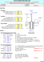
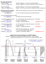
Pole Fdn (Czerniak) - Pole foundation analysis for free-top round piers using PCA/Czerniak method
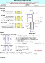
Pole Fdn (UBC-IBC) - Pole foundation analysis for free-top round piers using UBC/IBC method
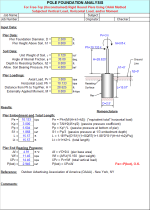
Pole Fdn (OAAA) - Pole foundation analysis for free-top round piers using OAAA method
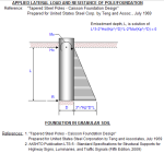
Granular Soil (Teng) - Pole foundation analysis in granular soil using USS/Teng method
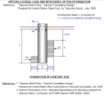
Cohesive Soil (Teng) - Pole foundation analysis in cohesive soil using USS/Teng method
Program Assumptions and Limitations:
1. Since there is not a universally accepted method for pole foundation analysis, this program offers up five (5) different methods of determining embedment length for pole foundations. The 'Pole Fdn(Czerniak)' worksheet is the primary method emphasized in this program, since it provides the most detail in overall analysis. However, it does yield the most conservative embedment depth results of all the methods presented.
2. The references used in the different analysis methods in this program are as follows:
a.'Design of Concrete Foundation Piers' - by Frank Randall Portland Cement Association (PCA) - Skokie, IL, May 1968
b.'Resistance to Overturning of Single, Short Piles' - by Eli Czerniak ASCE Journal of the Structural Division, Vol. 83, No. ST2, Paper 1188, March 1957
c.1997 Uniform Building Code (UBC), Section 1806.8, page 2-45
d.Outdoor Advertising Association of America (OAAA) - New York, NY
e.'Tapered Steel Poles - Caisson Foundation Design' Prepared for United States Steel Corporation by Teng and Associates, July 1969
f.AASHTO Publication LTS-5 - Standard Specifications for Structural Supports for Highway Signs, Luminaries, and Traffic Signals (Fifth Edition, 2009)
Note: references 'a' and 'b' refer to the 'Pole Fdn(Czerniak)' worksheet, while references 'e' and 'f' refer to both the 'Granular Soil(Teng)' and 'Cohesive Soil(Teng)' worksheets.
3. The 'Pole Fdn(Czerniak)' worksheet assumes that the foundation is short, rigid, meeting the criteria that the foundation embedment length divided by the foundation diameter = 10.
4. This program will handle both horizontally as well as vertically applied loads. The vertical load may have an associated eccentricity which results in an additional overturning moment which is always assumed to add directly to the overturning moment produced by the horizontal load.
5. This program assumes that the top of the pier is at or above the top of the ground surface level.
6. This program assumes that the actual resisting surface is at or below the ground surface level. This accounts for any weak soil or any soil which may be removed at the top.
7. The 'Pole Fdn(Czerniak)' worksheet assumes that the rigid pier rotates about a point located at a distance, 'a', below the resisting the surface. The maximum shear in pier is assumed to be at that 'a' distance, while the maximum moment in the pier is assume to be at a distance = 'a/2'.
8. The 'Pole Fdn(Czerniak)' worksheet calculates the 'plain' (unreinforced) concrete stresses, compression, tension, and shear in the pier. The respective allowable stresses are also determined based on the strength (f'c) of the concrete. This is done to determine if steel reinforcing is actually required. However, whether minimum reinforcing is to be used or not is left up to the user. The allowable tension stress in 'plain' concrete is assumed to be equal to 10% of the value of the allowable compressive stress.
9. The 'Pole Fdn(Czerniak)' worksheet calculates the actual soil bearing pressures along the side of the pier at distances equal to 'a/2' and 'L'. The respective allowable passive pressures at those locations are determined for comparison. However, it is left up to the user to determine the adequacy.
10. Since all overturning loads are resisted by the passive pressure against the embedment of the pier, this program assumes that the pier acts in direct end bearing to resist only the vertical loading. The bottom of pier bearing pressure is calculated, which includes the self-weight of the pier, assumed at 0.150 kcf for the concrete.
Calculation Reference
AISC
Calculation Preview
Full download access to any calculation is available to users with a paid or awarded subscription (XLC Pro).
Subscriptions are free to contributors to the site, alternatively they can be purchased.
Click here for information on subscriptions.
I have downloaded your POLEFDN. It is excellent program. I have a scenario, for the following conditions;
1. Can these design for Monoblock foundations, where
a. Foundation is 2mx2m (square).
b. Foundation is fully embedded, except for top 300mm which is above ground level.
c. Can units be changes to SI system.
This has been corrected.
You are absolutely right. I was using the "average" shear stress on a circular section (fv = V/A), when I should have been using the maximum value of the shear, fv = 4*V/(3*A), as you pointed out.
Per ACI, the allowable shear stress is Fv = 2*(phi)*f'c^(1/2), where phi is 0.75 for shear. Thus, again as you pointed out, that works out to be Fv = 2*0.75*f'c^(1/2) = 1.5*f'c^(1/2).
Thank you for bringing that to my attention. I will make the corrections and get the update reposted.
Alex
In the process, I also discovered that I had some inconsistency in the variable labeling that was used for the passive resistance parameter. I showed both "R" and "Pp" in different places, so I changed each occurrence of the variable to "R", as was used in the Czerniak reference.
The current version of this workbook is now version 2.3.
Actually, in substance the IBC has not changed for embedded pole-type foundations since the 2006 version of the Code. Only the table and section designations have changed.
The version of this workbook is now 2.2.
This added information was obtained via another reference that I recently came across, AASTO Publication LTS-5 - "Standard Specifications for Structural Supports for Highway Signs, Luminaries, and Traffic Signals (Fifth Edition, 2009). The material in this reference was essentially the same as the original Teng & Associates reference, but included the additional equations for maximum moment and location.
I was using a simple iterative approach to solve the polynomial equation for the theoretical embedment depth, "L". In Column V of the worksheet, I have what I term index numbers for each iterative evaluation of the expression to help isolate where the solution converges to zero. Problem was, I had an inadvertent small gap of numbers in the index numbers, and thus they were not completely sequential. One "lucky" gentleman had a design situation where his solution fell at that exact point where the gap in the index numbers occurred, and the solution crashed. Lucky for me he stumbled upon the problem.
This has now been corrected and this workbook is now version 2.0.

Alex