More Retaining Wall Calculations

Description
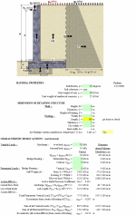
Let's break down the key components:
- Input Parameters:
- Soil Properties:
- Friction angle (φ) = 30 degrees
- Cohesion (c) = 0
- Soil unit weight (γb) = 18 kN/m³
- Concrete unit weight (γc) = 25 kN/m³
- Wall Dimensions:
- Wall height (H) = 6m
- Wall thickness (w) = 1m
- Footing width (B) = 7m
- Footing thickness (v) = 1m
- Toe width (t) = 2m
- Heel width (h) = 4m
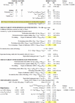
- Key Calculations: a) Forces Considered:
- Variable loads (surcharge)
- Self-weight of wall components
- Active earth pressure
- Soil weight over heel
b) Stability Checks:
- Sliding Check:
- Horizontal forces (HEd,dst) vs Frictional Resistance (HRd) - Degree of utilization = HEd,dst/HRd (should be <100%) - Results: 53% for A1 and 62% for A2 loading combinations- Overturning Check:
- Overturning moments vs Restoring moments - Degree of utilization = MEd,dst/MRd,fav - Results: 19% for A1 and 18% for A2- Bearing Capacity Check:
- Uses Meyerhof's method
- Considers shape factors, depth factors, and inclination factors
- Results: 20% utilization for A1 and 52% for A2
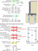
Pile design calculation for the retaining wall foundation:
- Pile Configuration:
- Diameter = 0.3m
- Reinforcement = 6 × Y12 bars (0.96% of concrete area)
- Edge clearance = 0.1m
- Lever arm (La) = 3.25m
- Spacing: 1.2m along toe, 1.45m along heel
- Load Distribution:
Design Loads (from wall analysis): - Vertical (VEd): A1 = 1097.0 kN/m, A2 = 822.0 kN/m - Horizontal (HEd): A1 = 233.5 kN/m, A2 = 217.7 kN/m - Moment (MEd): A1 = -161.8 kN-m/m, A2 = -11.7 kN-m/m- Individual Pile Loads:
Front Pile (Toe): - A1: 628.3 kN/pile - A2: 491.0 kN/pile Rear Pile (Heel): - A1: 831.4 kN/pile - A2: 598.6 kN/pile- Ultimate Bending Moment Resistance:
- Uses CP110 design interaction charts
- Calculated using normalized parameters (N/h²)
- Front Pile Mr,T: A1 = 41 kN-m/pile, A2 = 38 kN-m/pile
- Rear Pile Mr,H: A1 = 41 kN-m/pile, A2 = 36 kN-m/pile
- Horizontal Resistance:
- Uses Broms' method for lateral pile capacity
- Considers soil parameters:
- Sand density = 18 kN/m³
- No cohesion
- Friction angle: A1 = 30°, A2 = 24.8°
- Passive coefficient (Kp): A1 = 3.00, A2 = 2.44
- Design Check
Unit Horizontal Resistance (HRd): - A1: 89 kN/m - A2: 81 kN/m Utilization (ΛSTR,1 = HEd/HRd): - A1: 263% - A2: 270%The high utilization ratios (>100%) suggest that the pile design may need revision - either by increasing pile diameter, spacing, or reinforcement, as the horizontal loads exceed the calculated resistance.
Calculation Preview
Full download access to any calculation is available to users with a paid or awarded subscription (XLC Pro).
Subscriptions are free to contributors to the site, alternatively they can be purchased.
Click here for information on subscriptions.
Comments: 4
×
12 years ago
Dear Nephembani
I need to use your spreadsheet in English units
Please provide procedure on how to do this if possible
ss[/quote]
I need to use your spreadsheet in English units
Please provide procedure on how to do this if possible
ss[/quote]
12 years ago
Dear Nephembani
I need to use your spreadsheet in English units
Please provide procedure on how to do this if possible
BWM
I need to use your spreadsheet in English units
Please provide procedure on how to do this if possible
BWM


Sujan Singh