Stiffening ring for vessel under external pressure

Description
When pressure vessel exposed to external pressure stiffening rings used to avoid collapse.
External pressure could be due to vacuum conditions, or vessels inside a larger vessel.
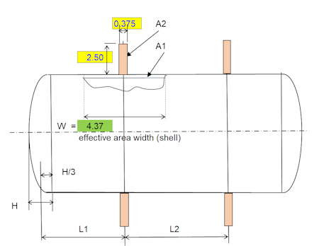
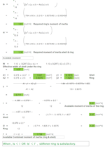
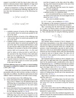
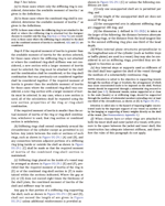
The program calculates the size of the rings and the max spacing allowed. Calculation done per ASME sec VIII Div. 1 UG-29
Design Data:
- Material: Specify the material used for the stiffening ring and shell.
- Stiffener size: Define the dimensions of the stiffening ring, including its cross-sectional profile (e.g., angle, T-section) and dimensions (e.g., height, thickness).
- Design Pressure (external): Indicate the maximum external pressure the shell and ring combination must withstand.
- Design temp: Specify the operating temperature of the system.
- OD shell: Define the outer diameter of the cylindrical shell.
- Min required shell thickness (ts less corrosion allowance): Provide the minimum allowable shell thickness after accounting for corrosion.
- Nominal shell thickness: Indicate the actual thickness of the shell material without corrosion allowance.
- Distance(s) of the stiffener rings: Specify the spacing between the stiffening rings along the shell's length.
- Elastic module at design temp: Provide the Young's modulus of the material at the design temperature.
UG-29 Design Principle:
UG-29 outlines the criteria for ensuring the cylindrical shell's stability under external pressure. Stiffening rings act as supports, dividing the shell into segments and preventing buckling between them.
Key Design Aspects:
- Buckling Analysis: The analysis determines the critical pressure at which the shell and ring combination buckles. UG-29 provides buckling formulas for various support conditions and stiffener geometries.
- Stiffener Strength: The stiffener itself must be strong enough to carry the induced load from the external pressure without failure.
- Stiffener Spacing: The spacing between the rings influences the buckling strength. Closer spacing leads to greater stability but increased fabrication cost. UG-29 provides guidance on selecting an appropriate spacing based on the shell geometry, material properties, and pressure load.
- Shell Thickness: UG-29 accounts for the interaction between the stiffening rings and shell thickness. Thicker shells can withstand higher pressures with wider stiffener spacing.
Additional Considerations:
- Fabrication tolerances: Account for manufacturing tolerances in the shell and stiffener dimensions during design calculations.
- Corrosion allowance: Select a suitable corrosion allowance based on the service environment and material susceptibility.
- Fatigue analysis: If cyclic loading is present, perform fatigue analysis to ensure the ring and shell can withstand repeated stress cycles.
Overall, the design of stiffening rings for cylindrical shells requires a careful balance between various factors. Understanding the principles outlined in UG-29 and performing accurate calculations is crucial for ensuring the structural integrity and safe operation of the pressure vessel.
Calculation Preview
Full download access to any calculation is available to users with a paid or awarded subscription (XLC Pro).
Subscriptions are free to contributors to the site, alternatively they can be purchased.
Click here for information on subscriptions.


