Monorail Design
Description
Excel Spreadsheet for design of monorail in offshore industry .
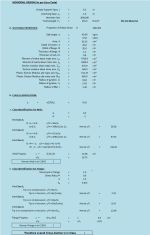
MONORAIL DESIGN( As per Euro Code)
SECTIONAL PROPERTIES:
CLASS CLASSIFICATION:
Class Identification For Web:
Web Property:
Class Identification For Flange:
Flange Property:
LOAD CALCULATION for ULS - B :
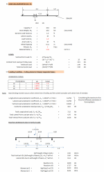
LOADS:
Loading Condition - Trolley placed at Simply Supported Span :
Reactions & Moments due to Vertical Loads:
Reactions & Moments due to Lateral Loads:
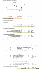
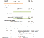
Stress Check 1 :- Capacity check
Check for Combine Stresses :
For Axial Force:
For Bending Moment about Minor axis:
For Bending Moment about Major axis:
Imperpection factor;
Non-dimensional slenderness ÝLT, for rolled section;
Moment resistance of section about major axis;
Combine U/C Ratio:
Check for Vertical Shear Force :
Slenderness Check:
Deflection Check:
Stress Check 2 :- Beam stress check @ Bottom flange
The design resistance of bottom flange,
Effective length:
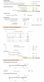
Loading Condition Trolley placed at Overhang :
Reactions & Moments due to Vertical Loads:
Reactions & Moments due to Lateral Loads:
Stress Check 1 :- Beam stress check @ Top flange
Check for Combine Stresses :
For Axial Force:
For Bending Moment about Minor axis:
For Bending Moment about Major axis:
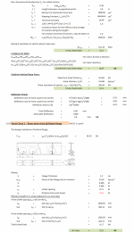
The designed buckling resistance moment for laterally unrestrained beam is given as:
Imperfection factor;
Non-dimensional slenderness ÝLT, for rolled section;
Moment resistance of section about major axis;
Combine U/C Ratio:
Check for Vertical Shear Force :
Deflection Check:
Stress Check 2 :- Beam stress check @ Bottom flange
The design resistance of bottom flange,
Effective length for a wheel adjacent to an end stop;
if the wheel spacing xw=>2√2 (m+e)+xe
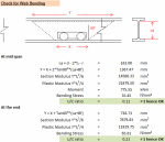
Check for Web Bending
At mid span
At the end
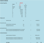
DESIGN OF HANGERS
Section Properties
Design Load
Horizontal Load
Bending Moment
Section Resistance
DESIGN OF BOLTS
Bolt Class
Material factor, ým2
Yield Strength fyb
Ultimate Tensile Strength fub
BOLT Classification
Diameter of Bolt, d
Diameter of Hole, do
Edge distance from centre of a fastner hole to the adjacent edge of any part in line of load,e1 =
Edge distance from centre of a fastner hole to the adjacent edge of any part at right angle to load,e2 =
Spacing between centres of fastners in line of load, P1
Spacing between centres of fastners perpendicular to load, P2
Area of Bolt, A
No of Bolts per connection
Axial Load for Bolt Design,Ft.Ed
Shear Force perpendicular to monorail , Fv.Ed
Shear Force along the monorail,Fv.Ed
Shear Resistance per shear plane:
Tension Resistance of bolt:
Bearing Resistance:
Punching Shear Resistance:
Calculation Reference
Offshore Engineering
Structural Design
Monorail Overhead Lifting
Calculation Preview
Full download access to any calculation is available to users with a paid or awarded subscription (XLC Pro).
Subscriptions are free to contributors to the site, alternatively they can be purchased.
Click here for information on subscriptions.

