Lifting Lug BS EN 1993-1-8

Description
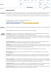
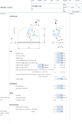
This spreadsheet is a simple aid to designing lugs BS EN 1993-1-8. It assumes that the shackle pin is designed and tested by the lifting gear supplier. It only covers the lug - separate calculations will be needed for the fixing of lug bases to the lifted member. The spreadsheet calculates the lug capacity in bearing, tension, and shear and then checks for combined stresses and the weld section modulus. It is useful for bespoke lifting lugs for lifting structural members and for lugs on lifting beams. But probably not much good for anything else.
A lifting lug design needs to be checked for several failure modes:
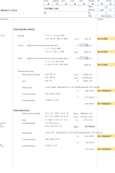
- Bearing Resistance at Pin Hole
- Calculated using the edge distance ratio (α_d), which is the edge distance divided by 3 times the hole diameter
- The bearing resistance F_b_Rd = 2.5 × α_d × fu × t × d / γM2
- Where fu is ultimate strength, t is thickness, d is hole diameter, and γM2 is the partial safety factor (typically 1.25)
- Tension Resistance
- Check both gross and net sections
- Gross section: N_pl_Rd = A_gross × fy / γM0
- Net section: N_u_Rd = 0.9 × A_net × fu / γM2
- Design tension resistance is the lower of these two values
- A_net is the cross-sectional area minus the hole
- Shear Resistance
- Uses the net shear area (thickness × width minus hole)
- V_Rd = A_v × fy / (√3 × γM0)
- Where A_v is the shear area and fy is yield strength
- Combined Stresses
- Uses von Mises criterion
- σ_eq = √(σ_t² + 3τ²)
- Where σ_t is tensile stress and τ is shear stress
- Must be less than fy/γM0
- Weld Design
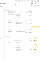
- Uses effective throat thickness (a = 0.7071 × leg length for 45° fillet welds)
- Checks combined normal and shear stresses
- Uses correlation factor β_w (0.85 for S275, 0.9 for S355 and above)
- Design strength f_vw,d = fu / (√3 × β_w × γM2)
Material Properties:
- S275: fy = 275 N/mm², fu = 430 N/mm²
- S355: fy = 355 N/mm², fu = 510 N/mm²
- S420: fy = 420 N/mm², fu = 520 N/mm²
- S460: fy = 460 N/mm², fu = 540 N/mm²
Important Design Considerations:
- Edge distances should be sufficient to prevent tear-out
- Thickness should be adequate for bearing stresses
- Width should provide enough net section area
- Weld size and length must be sufficient for loads
- Consider both in-plane and out-of-plane forces if present
The design is acceptable when all utilization ratios are less than 1.0, meaning the applied stresses are below the allowable limits for each failure mode.
Calculation Preview
Full download access to any calculation is available to users with a paid or awarded subscription (XLC Pro).
Subscriptions are free to contributors to the site, alternatively they can be purchased.
Click here for information on subscriptions.


