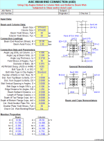
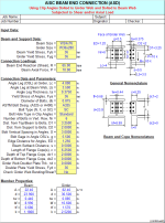
CLIPCONN.xls
Description
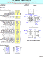
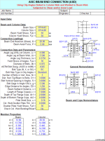
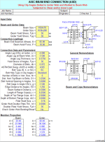
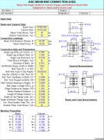
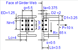
"CLIPCONN" is a spreadsheet program written in MS-Excel for the purpose of analysis of steel beam end connections using double clip angles either welded or bolted to the beam web, and bolted to either the column flange, column web, or girder web. The connections may be subjected to end shear reaction and/or axial load. Specifically, all applicable "limit states" for the end connection analysis pertaining to the clip angles, bolts, beam web, column flange or web, and girder web are checked.
This program is a workbook consisting of eight (8) worksheets, described as follows:
- Documentation
- Welded Clips(Col Flg) - Clip angles welded to beam web and bolted to column flange
- Welded Clips(Col Web) - Clip angles welded to beam web and bolted to column web
- Welded Clips(Girder) - Clip angles welded to beam web and bolted to girder web
- Bolted Clips(Col Flg) - Clip angles bolted to beam web and bolted to column flange
- Bolted Clips(Col Web) - Clip angles bolted to beam web and bolted to column web
- Bolted Clips(Girder) - Clip angles bolted to beam web and bolted to girder web
- Uncoped Beam Table - End shear reaction capacities for uncoped beams using clip angles
Program Assumptions and Limitations:
1. This program follows the procedures and guidelines of the AISC 9th Edition Allowable Stress (ASD) Manual (1989) and the AISC 9th Edition Manual Vol. II - Connections (1992).
2. This program uses the database of member dimensions and section properties from the "AISC Shapes Database", Version 3.0 (2001) as well as the AISC 9th Edition (ASD) Manual (1989).
3. This program assumes that the tension capacity for any "limit state" is reduced by the presence of shear. For allowable bolt tension in the presence of shear, the "interaction" (combined stresses) is handled directly by the AISC Code equations. For other "limit states" in combined stresses such as bolt bearing, gross and net shear and tension, and block shear and tension tearout, the effect of "interaction" is handled by use of the formula, P/Ra+(R/Rv)^2=1, as suggested from the following reference:
"Combined Shear and Tension Stress" - by Subhash C. Goel, AISC Journal, 3rd Qtr.-1986.
Thus, the reduction factor applied to the tension "limit state" capacity is = (1-R/Rv)^2.
where:R = actual shear end reaction
Rv = allowable shear capacity for the particular "limit state" considered
4. This program follows the procedure for "yield line" theory for the flexural analysis of either a column web or a girder web subjected to an axial load, as outlined in "Connections" by Larry S. Muir and William A. Thornton and published by Cives Steel Company.
Note: This booklet is a reprint of Chapter 3, from the "Structural Steel Designer's Handbook, 4 th Edition.
5. This program contains numerous “comment boxes” which contain a wide variety of information including explanations of input or output items, equations used, data tables, etc. (Note: presence of a “comment box” is denoted by a “red triangle” in the upper right-hand corner of a cell. Merely move the mouse pointer to the desired cell to view the contents of that particular "comment box".)
Calculation Reference
AISC
Calculation Preview
Full download access to any calculation is available to users with a paid or awarded subscription (XLC Pro).
Subscriptions are free to contributors to the site, alternatively they can be purchased.
Click here for information on subscriptions.
It's odd, because I normally do the calculations off to the right and keep them hidden, and then merely reference the appropriate cells in the displayed results on the main page. In cell B135, for some reason the logic was in that cell but it was incorrect and inconsistent. What I intended to do was reference cell N75 in cell B135, but that did not get done for some reason. The logic in cell N75 was actually correct, in taking the maximum of the angle leg thickness and the beam web thickness to determine the minimum fillet weld size per the AISC 9th Edition ASD Manual.
The current version is now 2.2.
The "C" coefficient value for a=2.40 and k=1.6 should have been 0.874, but was inadvertently shown as 0.847.
This has been corrected as required in all three of the following workbooks:
"WELDGRP.xls" - now version 2.3
"CLIPCONN.xls" - now version 2.1
"ClipConnTable.xls" - now version 1.6
Hey, you can't fault me for not being consistent!!! (LOL)
You response makes a lot of sense, and thanks again for sharing you expertise.
I have been impressed with Cives in the past in reviewing some of their work and detail shop drawings. The "Design guides" you mention.... I tried doing a GOGGLE search for similar sounding publications by Cives. Are they available to the public to your knowledge?
In the worksheets for clip angles bolted to a column web, the bolted legs of the clips are checked for bending due to prying action. The web of the column is checked for bending using "yield line" theory that I "borrowed" from Cives Steel design guides.
In the worksheets for connections to a girder web, the user has the option to check (yes/no) the bending in the web. Typically there is no transfer, "pass-through", force for a beam "dead-ending" into a girder, with no beam on the other side of the girder web. But again, the choice is left up to the user.
Alex

