AISC 14.1 Properties Viewer.xls

Description
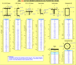
This workbook is based on the "AISC Shapes Database" Version 14.1 (October 2013), and has the same look as the ones that I did based on earlier AISC shapes database/manual versions.
Here is a link to the AISC.org website where the source database file can be found:
http://www.aisc.org/content.aspx?id=2868
NOMENCLATURE FOR AISC VERSION 14.1 MEMBER PROPERTIES AND DIMENSIONS:
A = Cross-sectional area of member (in.^2)
d = Depth of member, parallel to Y-axis (in.)
h = Depth of member, parallel to Y-axis (in.)
tw = Thickness of web of member (in.)
bf = Width of flange of member, parallel to X-axis (in.)
b = Width of member, parallel to X-axis (in.)
tf = Thickness of flange of member (in.)
k = Distance from outer face of flange to web toe of fillet (in.)
k1 = Distance from web centerline to flange toe of fillet (in.)
T = Distance between fillets for wide-flange or channel shape = d(nom)-2*k(det) (in.)
gage = Standard gage (bolt spacing) for member (in.) (Note: gages for angles are available by viewing comment box at cell K18.)
Ix = Moment of inertia of member taken about X-axis (in.^4)
Sx = Elastic section modulus of member taken about X-axis (in.^3)
rx = Radius of gyration of member taken about X-axis (in.) = SQRT(Ix/A)
Iy = Moment of inertia of member taken about Y-axis (in.^4)
Sy = Elastic section modulus of member taken about Y-axis (in.^3)
ry = Radius of gyration of member taken about Y-axis (in.) = SQRT(Iy/A)
Zx = Plastic section modulus of member taken about X-axis (in.^3)
Zy = Plastic section modulus of member taken about Y-axis (in.^3)
rts = SQRT(SQRT(Iy*Cw)/Sx) (in.)
xp = horizontal distance from designated member edge to plastic neutral axis (in.)
yp = vertical distance from designated member edge to plastic neutral axis (in.)
ho = Distance between centroid of flanges, d-tf (in.)
J = Torsional moment of inertia of member (in.^4)
Cw = Warping constant (in.^6)
C = Torsional constant for HSS shapes (in.^3)
a = Torsional property, a = SQRT(E*Cw/G*J) (in.)
E = Modulus of elasticity of steel = 29,000 ksi
G = Shear modulus of elasticity of steel = 11,200 ksi
Wno = Normalized warping function at a point at the flange edge (in.^2)
Sw = Warping statical moment at a point on the cross section (in.^4)
Qf = Statical moment for a point in the flange directly above the vertical edge of the web (in.^3)
Qw = Statical moment at the mid-depth of the section (in.^3)
x(bar) = Distance from outside face of web of channel shape or outside face of angle leg to Y-axis (in.)
y(bar) = Distance from outside face of outside face of flange of WT or angle leg to Y-axis (in.)
eo = Horizontal distance from the outer edge of a channel web to its shear center (in.) = (approx.) tf*(d-tf)^2*(bf-tw/2)^2/(4*Ix)-tw/2
xo = x-coordinate of shear center with respect to the centroid of the section (in.)
yo = y-coordinate of shear center with respect to the centroid of the section (in.)
ro(bar) = Polar radius of gyration about the shear center = SQRT(xo^2+yo^2+(Ix+Iy)/A) (in.)
H = Flexural constant, H = 1-(xo^2+yo^2)/ro(bar)^2)
LLBB = Long legs back-to-back for double angles
SLBB = Short legs back-to-back for double angles
h(flat) = The workable flat (straight) dimension along the height, h (in.)
b(flat) = The workable flat (straight) dimension along the width, b (in.)
A(surf) = The total surface area of a rectangular or square HSS section (ft.^2/ft.)
STD = Standard weight (Schedule 40) pipe section
XS = Extra strong (Schedule 80) pipe section
XXS = Double-extra strong pipe section
Calculation Reference
AISC MEMBER PROPERTIES AND DIMENSIONS
Steel Design
Structural Steel
Calculation Preview
Full download access to any calculation is available to users with a paid or awarded subscription (XLC Pro).
Subscriptions are free to contributors to the site, alternatively they can be purchased.
Click here for information on subscriptions.


