Thermal Stresses in Cylindrical Shells at a Uniform Temperature restrained at one edge

Description
Analytical methods are used to calculate thermal stresses for the case of a cylindrical shell wall at a uniform temperature, fully restrained at one edge.
Thermal Stresses in Cylindrical Shells
Case: Cylindrical Shell at a uniform temperature, fully restrained at one end
Introduction
If a cylindrical shell with free edges undergoes a uniform temperature change then no thermal stresses will be produced. If an edge of the cylinder is clamped, however, then free expansion is prevented and local bending stresses are produced at the
clamped edge.These stresses tend towards zero away from the clamped edge as the cylinder wall recovers its free radial thermal expansion.
In this spreadsheet analytically determined thermal stresses are calculated along the cylinder wall for the case of a cylinder at a uniform temperature that is fully restrained at one edge. The stresses and displacements are calculated using the methods of Timoshenko
and Woinowsky(1). Results are verified for the example given using approximate numerical methods of the finite element code Abaqus(2).
For full restraints the shell is assumed to be restrained both radially and rotationally at one end. An example of this may be where the shell is attached to an end plate which could be assumed to be relatively stiff or where the end of the cylinder is bolted down.
Calculation Input
Data input on the 'Calculation' worksheet is the cylinder geometry of mean radius and shell thickness; material properties of Young's Modulus Coefficient of thermal expansion, and Poisson's ratio; and lastly the shell temperarture.
Note that material properties should be selected for the shell temperature input.
The user can select the units to be used in the analysis from a drop down list. These are labeled as either 'mm' or 'in' and are for convenience only.
The appropriate selection will simply change the units listed in the input and calculated values.
Output
Stresses and radial displacements are calculated at the restrained position and along the length of the cylinder to a distance where the change in stress is considered to be negligible. This is taken to be approximately 6 wavelengths along the shell wall, where the wavelength is a
Radial displacements and all stress companents are calculated, including hoop (circumferential) stress, axial and radial stress at both inner and outer surfaces. For convenience the membrane and bending stress companents that make up the surface stresses are also calculated.
The Von Mises stress intensity is also calculated at the surface positions. These surfaces are labelled as SNEG and SPOS, in line with the Abaqus convention.
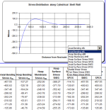
The results are shown in the 'calculation' sheet in two charts. One shows the radial displacement along the shell wall away from the restraint, and the second shows the calculated stress. A drop down list allows the user to select which stress category they wish to display.
The complete set of stresses are shown in the 'ResultsChart' sheet.
Assessment of stresses - guidelines
If the cylinder wall forms part of a pressure vessel then the stresses calculated using this method are classified as secondary.
Primary stresses due to mechanical loads, such as pressure loads, need to be combined with these results for assessment against pressure design code limits.
In general the combined primary and secondary stresses are limited to twice yield. Refer to the appropriate design code for guidance on stress classification and limits.
References:
1. Timoshenko and Woinowsky, Theory of Plates and Shells
2. Abaqus v6.13, Dassault Systemes, www.simulia.com/
Calculation Reference
Theory of Plates and Shells
Timoshenko and Woinowsky
Thermal Stress Analysis
Calculation Preview
Full download access to any calculation is available to users with a paid or awarded subscription (XLC Pro).
Subscriptions are free to contributors to the site, alternatively they can be purchased.
Click here for information on subscriptions.


