Tank nozzle stress analysis following API 650 appendix P
Description
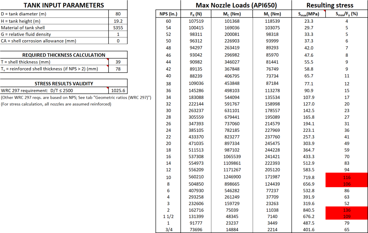
Using this tool you can determine stresses at the nozzle connection of low pressure storage tanks. Either use the maximum allowable tank loads calculated as per API 650 appendix P (which are also calculated based on your base tank parameters) or put in your own loads to calculate the resulting stresses. This tool has been validated by comparing results with that of Nozzlepro (FEA) and Caesar II.
To determine the stresses at the nozzle connection of low-pressure storage tanks, you can follow these steps:
1. Understand the Basics
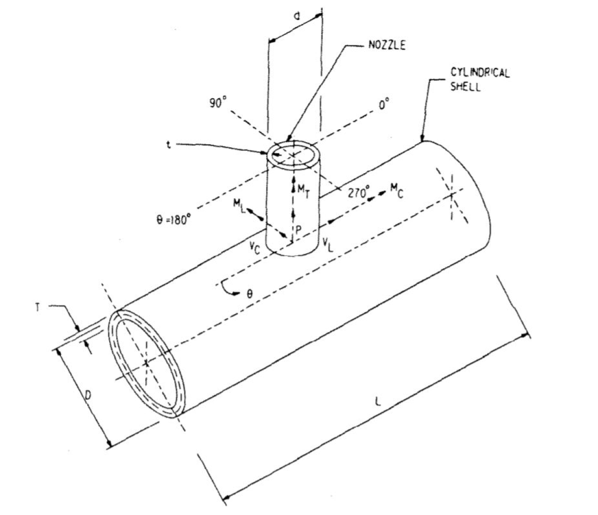
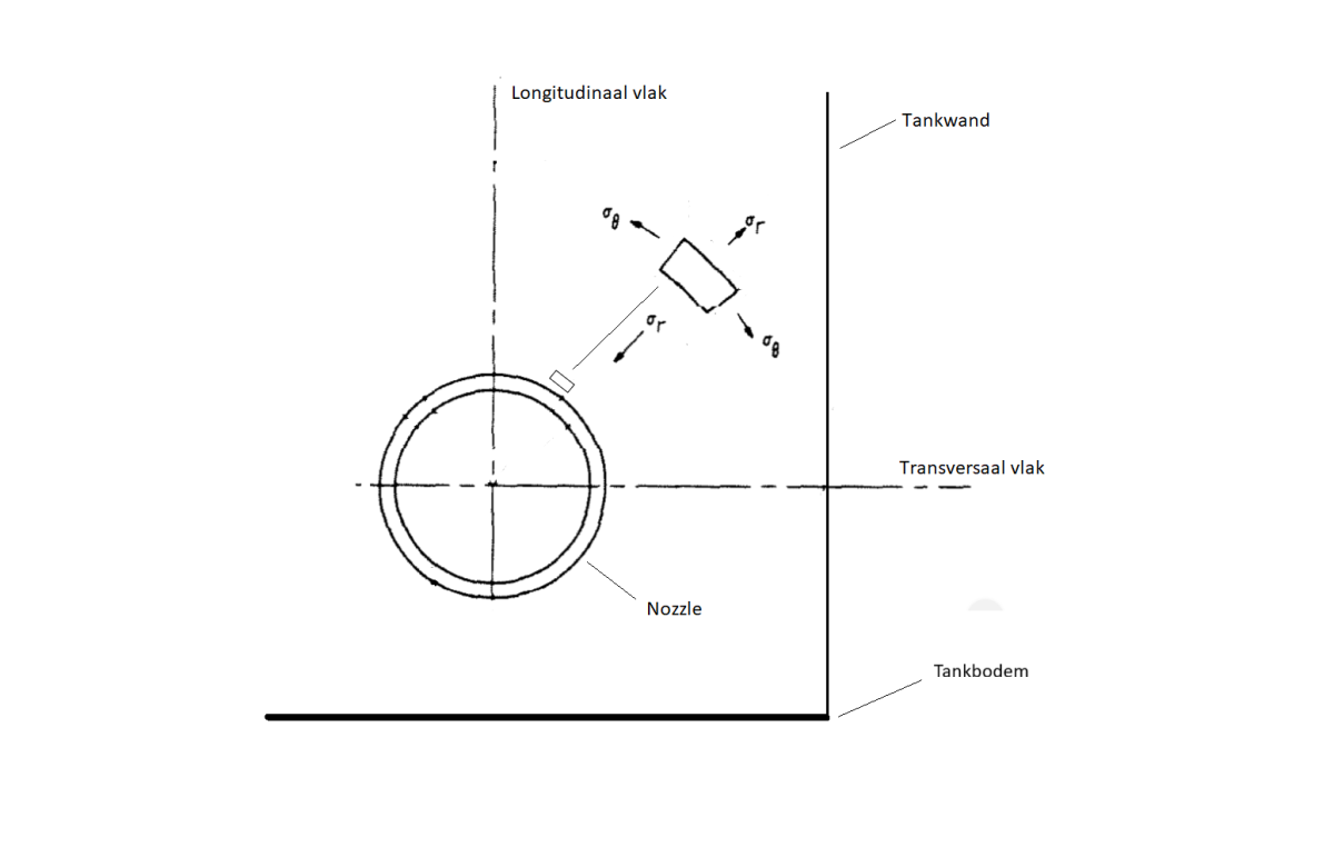
- Nozzle Connection: This is where pipes connect to the tank, allowing fluid to enter or exit.
- Stresses: These are forces per unit area within the tank material, which can be caused by internal pressure, external loads, or thermal expansion.
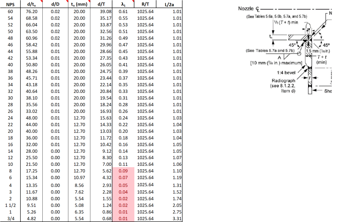
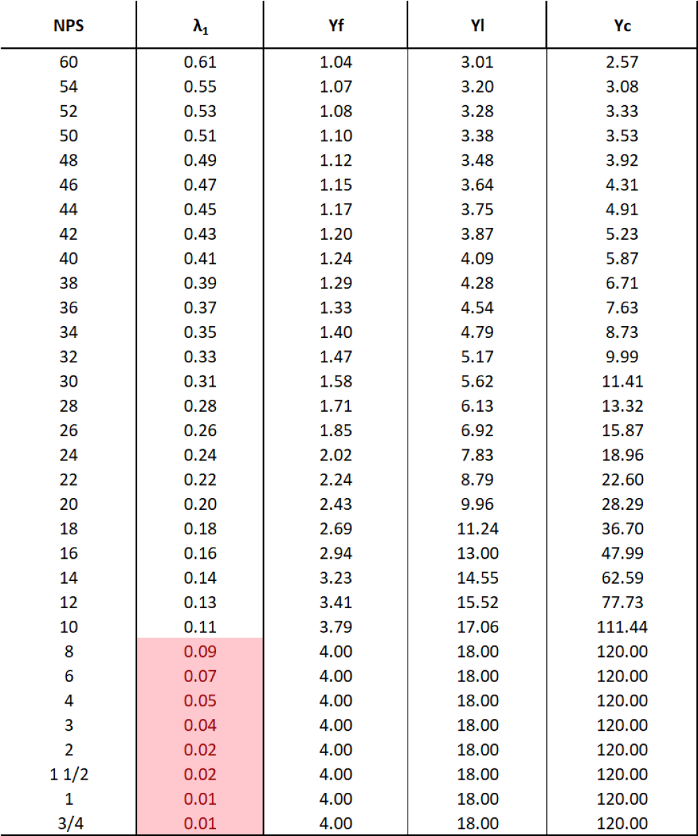
2. API 650 Appendix P
API 650 Appendix P provides guidelines for calculating the maximum allowable loads on tank nozzles. These loads are based on the tank’s design parameters, such as material, thickness, and dimensions.
3. Calculate Maximum Allowable Loads
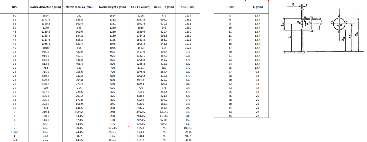
- Determine Base Parameters: Identify the tank’s material, thickness, diameter, and operating conditions.
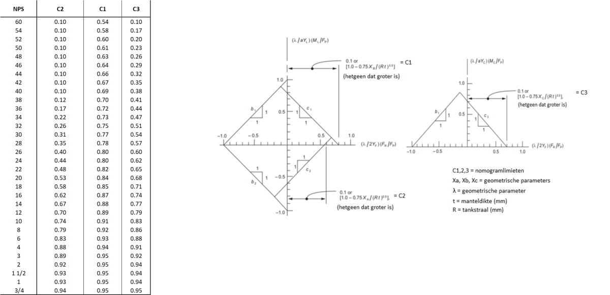
- Use API 650 Appendix P: Follow the procedures outlined to calculate the maximum allowable loads on the nozzle. This involves considering factors like internal pressure, external forces, and moments.
4. Apply Loads to Calculate Stresses
- Input Loads: Use the maximum allowable loads calculated or input your own loads based on operational conditions.
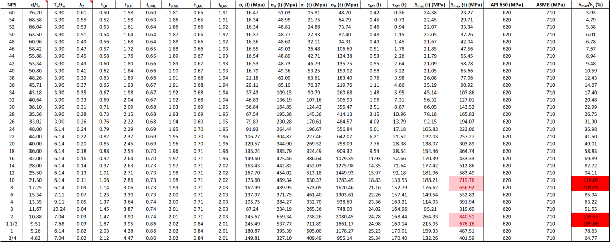
- Stress Analysis: Perform a stress analysis using methods like finite element analysis (FEA) or analytical calculations. This involves evaluating the stresses in the nozzle and the surrounding tank shell.
5. Compare with Allowable Stresses
- Allowable Stresses: Compare the calculated stresses with the allowable stress limits for the tank material. These limits are typically provided in design codes like ASME Section VIII or API 650.
Example Calculation
-
Determine Base Parameters:
- Material: Carbon Steel
- Thickness: 10 mm
- Diameter: 5 meters
- Operating Pressure: 1 bar
-
Calculate Maximum Allowable Loads (using API 650 Appendix P):
- Axial Load: 5000 N
- Shear Load: 3000 N
- Bending Moment: 2000 Nm
-
Perform Stress Analysis:
- Input the loads into a stress analysis software or use analytical methods.
- Calculate the resulting stresses at the nozzle connection.
-
Compare with Allowable Stresses:
- Allowable Stress for Carbon Steel: 150 MPa
- Ensure the calculated stresses do not exceed this limit.
By following these steps, you can determine the stresses at the nozzle connection and ensure they are within safe limits. If you need more detailed guidance or specific calculations, consulting a structural engineer or using specialized software might be beneficial.
Calculation Preview
Full download access to any calculation is available to users with a paid or awarded subscription (XLC Pro).
Subscriptions are free to contributors to the site, alternatively they can be purchased.
Click here for information on subscriptions.