Taki FE Spreadsheet 02 - bolted_joint_070506.xls

Description
Finite Element Example - Bolted Joint Analysis
Written by Toshimi Taki Prepared on May 6, 2007
Note: This Excel file can be modified to solve any 2D problem using the following elements:
Rod with 2 end points, "ROD"
Traiangular element with 3 grid points, "TRIA3"
Quadrilateral element with 4 grid points, "QUAD4"
Spring elements, "SPRING"You may also be interested in a discussion with the author posted in the Site News.
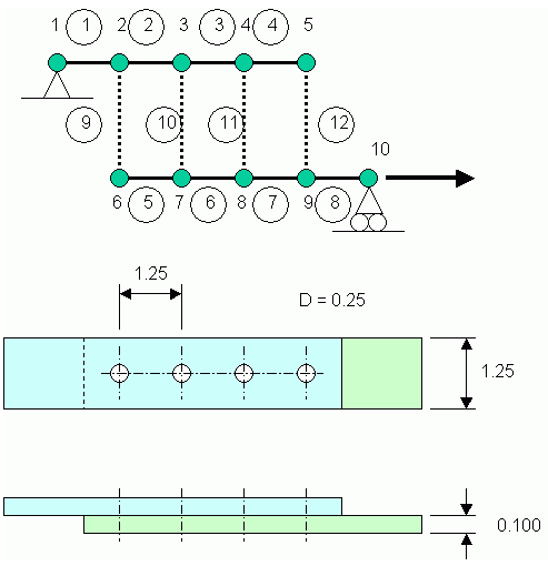
Energy method combined with MS-Excel Solver to solve bolted joints is presented as an example. Example Problem and Modelling Bolted joint is modelled as described in reference [1]. The plates or sheets are modelled as rods which are axial force elements. The bolts are modelled as springs which transfer shear force. Single lap joints which are supported in out-of-plane direction are analysed. See figure opposite. The plates are made of aluminium alloy and the bolts are made of low alloy steel. All dimensions are in inches.
Equivalent Joint Stiffness - The spring constant (or equivalent joint stiffness), K for bolted joint is calculated as follows (Reference [1]). Note that the definition of plate thickness is different from Reference [1]. The first term is bending compliance of the bolt, the second term is shear compliance of the bolt and the third term is bearing compliance of the plates.
Reference
[1] M. B. Tate and S. J. Rosenfeld, Preliminary Investigation of the Loads Carried by Individual Bolts in Bolted Joints, NACA TN 1051, 1946. (This paper can be downloaded from NASA report server.)
Calculation Reference
Bruhn
Finite Element
Calculation Preview
Full download access to any calculation is available to users with a paid or awarded subscription (XLC Pro).
Subscriptions are free to contributors to the site, alternatively they can be purchased.
Click here for information on subscriptions.
