IBC2009E.xls

Description
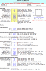
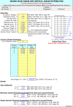
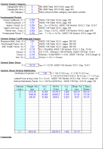
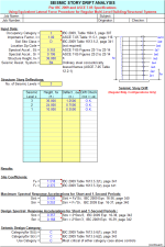
"IBC2009E" is a spreadsheet program written in MS-Excel for the purpose of seismic loading analysis for buildings and various nonbuilding structures, as well as architectural, mechanical, and electrical components per the IBC 2009 and ASCE 7-05 Codes. Specifically, the total base seismic shear for buildings and nonbuilding structures is calculated. For Multi-Level Buildings, the vertical distribution of the total seismic shear is also determined, and a drift analysis can also be performed.. The seismic restraint force for various components is also calculated. Seismic maps are also included.
This program is a workbook consisting of thirteen (13) worksheets, described as follows:
| Worksheet Name | Description |
| Doc | Documentation sheet |
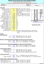
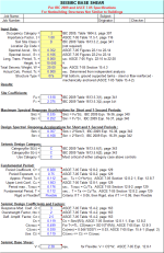
| Single-Level Bldg. | Seismic base shear for single-level buildings |
| Multi-Level Bldg. | Seismic base shear and vertical shear distribution for multi-level buildings |
| Multi-Level Bldg. (Drift) | Seismic story drift analysis for multi-level buildings |
| Vert. Tank or Vessel | Seismic base shear and overturning moment for vertical tanks/vessels |
| Nonbldg. Struct. | Seismic base shear for nonbuilding structures |
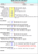
| Arch. Components | Seismic forces for architectural components |
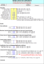
| M & E Components | Seismic forces for mechanical and electrical components |
| 2002 USGS Maps for Ss | 2002 USGS maps for 0.2 sec. spectral acceleration with 2% P.E. in 50 yrs. |
| 2002 USGS Maps for S1 | 2002 USGS maps for 1.0 sec. spectral acceleration with 2% P.E. in 50 yrs. |
| ASCE 7-05 Maps for TL | ASCE 7-05 Code maps for Long-Period Transition Period |
| 2008 USGS Maps for Ss | 2008 USGS maps for 0.2 sec. spectral acceleration with 2% P.E. in 50 yrs. |
| 2008 USGS Maps for S1 | 2008 USGS maps for 1.0 sec. spectral acceleration with 2% P.E. in 50 yrs. |
Program Assumptions and Limitations:
1. This program uses the IBC 2009 Code only to determine the Seismic Design Category, while IBC 2009 Code Section 1613.1 permits the Seismic Design Category to be determined by either IBC 2009 or ASCE 7-05. For all practical purposes, beyond determining the Seismic Design Category, the IBC 2009 Code defers to the ASCE 7-05 Code for seismic analysis and design.
2. This program incorporates the changes provided in Supplement No. 2 to the ASCE 7-05 Code.
3. For buildings, the program assumes the use of the equivalent lateral-force method for analysis, per ASCE 7-05 Section 12.8. For nonbuilding structures, ASCE 7-05 Section 15.0 is followed. For architectural, mechanical, and electrical components, ASCE 7-05 Section 13.0 which is followed. The "simplified" method, per ASCE 7-05 Section 12.14 is not used in any of the calculation worksheets.
4. The program assumes "regular" buildings and structures, with plan and vertical irregularities not being considered. Refer to ASCE 7-05 Section 12.3 for building configuration, and plan and vertical irregularity criteria.
5. Worksheets for Multi-Level Buildings are applicable for buildings and structures up to 240 feet in height, with up to 15 levels. (Story deflections are to be determined from separate elastic 2D or 3D frame analysis.)
6. This program does not include the provisions for nonbuilding structures that are supported by other structures as per ASCE 7-05 Section 15.3.
7. Worksheets calculate for "gross" seismic shear force, and do not reflect the use of any load factors. Refer to ASCE 7-05 Section 12.4 for applicable loads factors for LRFD or strength design as well as ASD analysis.
8. USGS 2002 maps for the short term 0.2 sec. spectral acceleration (SA) with 2% Probability of Exceedance in 50 years, Ss, as well as the 1.0 sec. spectral acceleration (SA) with 2% Probability of Exceedance in 50 years, S1, are included. These maps are the 2002 "color versions" of Figures 22-1 and 22-2 from ASCE 7-05. Peak gravitational acceleration, PGA, is what is experienced by a particle on the ground. Response spectral acceleration, SA, is what is approximately experienced by a building, as modeled by a particle on a massless vertical rod having the same natural period of vibration as the building.
The SA values shown in the USGS maps as well as the ASCE 7-05 Figures 22-1 through 22-14 are expressed as a percentage of "g", the acceleration due to gravity. Their numerical values should be divided by 100 to convert them into decimal form for use in the Code formulas and calculations. Note that there are "exploded" maps of various portions of continental U.S. included as well. These can be seen by scrolling down screen. (Note: while the USGS does have more current gridded design values for Ss and S1 available at their web site, the user is cautioned in their use as they are NOT officially adopted for use by the ASCE 7-05 Code. If their use would result in a lower Seismic Design Category and reduced seismic loads, the user is advised to seek formal approval of their use by the owner and building official if applicable.)
9. This program allows the user to select only site classes "A" through "E", since site class "F" requires site-specific geotechnical investigation and dynamic site response analyses. These same requirements also apply for site class "E", but only when Ss >= 1.25g and S1 >= 0.5g.
10. In the calculation worksheets, a "hyperlink" is provided to take the user directly to the USGS website at:
Calculation Preview
Full download access to any calculation is available to users with a paid or awarded subscription (XLC Pro).
Subscriptions are free to contributors to the site, alternatively they can be purchased.
Click here for information on subscriptions.
I know that C.d is used since an increase in R drives you into the inelastic world.
In other words, if I use R = 6 (and thus 341) I must then multiply all my FEA model deflections by 5x, even though no stress levels in my FEA model reach yield?
Likewise, with ?.o, I'd need to take any loads/stresses in my braces and multiply them by 2, since design loads as per 341 require "amplified seismic load".
Rahul
This workbook is now version 1.1.

