DESIGN OF CANTILEVER RETAINING WALL PER ACI318-05
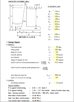
Description
Material
Concrete grade
Steel grade
Material factor
Conrete density
Soil density
Angle of repose for soil
Coefficient of active earth pressure ka =
Coefficient of passive earth pressure ka =
Safe Bearing Capacity
Coeff of friction for Sliding
Loading
Surcharge pressure
F.S against Overturning
F.S against Sliding
Max. bearing pressure
Wall Main reinforcement
Heel Top Main reinforcement
Toe bottom main reinforcement
Design Output
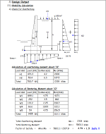
Stability Calculation
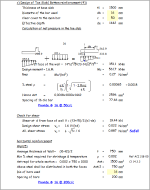
Check for Overturning
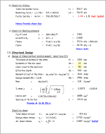
Check for Sliding
Total Horizontal force
Restoring force =
Factor Safety
Check for Bearing pressure
C.g of Load
eccentricity
fbmax
fbmin
Structural Design
Design of Stem (vertical reinforcement - inner face-(1))
Thickness at bottom of the stem
Diametre of the bar used
Clear cover to the main bar
Effective depth
Moment at root of the stem =
Design moment Mu = 1.6.M
Rmz
Check for shear
Total shear at root
Design shear stress
All. shear stress
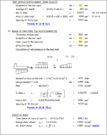
Wall vertical reinforcement - Outer face (2)
Diametre of the bar used
Average eff depth
Min % steel
Area of steel reqd
Spacing of 16 dia bar
Design of Heel Slab( Top reinforcement-(3))
Thickness at base slab
Diametre of the bar used
Clear cover to the main bar
Effective depth
Calculation of net pressure in the heel slab
Check for shear
Total shear at face of wall
Design shear stress
All. shear stress
c) Design of Toe Slab( Bottom reinforcement (4))
Thickness at base slab
Diametre of the bar used
Clear cover to the main bar
Effective depth
Calculation of net pressure in the toe slab
Check for shear
Shear at d from face of wall
Design shear stress
All. shear stress
horizontal reinforcement
Wall(5)
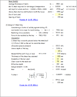
Average thickness of Wall
Min % steel required for shrinkage & temperature
Ast reqd for whole section =
Above steel shall be distributed in both the faces
Dia of bars used
Spacing of bars
Base Slab(6)
Average thickness of Wall
Min % steel required for shrinkage & temperature
Ast reqd for whole section =
Above steel shall be distributed in both the faces
Dia of bars used
Spacing of bars
d) Design of Shear Key
Considering a factor of safety against sliding 1.5.
Horizontal force reqd. to resist sliding
Restoring force available
Force to be resisted by the key
Assumption
i) Shear key is exactly placed below the stem/wall
ii) 2/3rd of SBC on the soil to resist the shear
Allowable passive pressure
Hence depth of the key
Moment @ the bott. Face of slab
Thickness of the shear key assumed
Diametre of the bar used
Clear cover to the maib bar
Effective depth
Design moment = 1.6.M
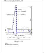
Structural Details of Retaining Wall
Calculation Reference
Concrete Design
Beam Design
Retaining Wall
Calculation Preview
Full download access to any calculation is available to users with a paid or awarded subscription (XLC Pro).
Subscriptions are free to contributors to the site, alternatively they can be purchased.
Click here for information on subscriptions.

