Base Plate Design (Biaxial Bending) - AISC 360-16 LRFD

Description
The MS-Excel spreadsheet program designed for the analysis of steel column base plates serves as a comprehensive engineering tool catering to a range of loading scenarios. In the realm of structural engineering, column base plates encounter diverse forces, including axial loads in compression or tension, coupled with major and/or minor-axis column bending, and major and/or minor-axis shear. The primary objective of this tool is to conduct a rigorous analysis, ensuring the integrity and safety of the column base plates under these varying conditions.
The spreadsheet performs meticulous checks on critical parameters such as base plate bearing pressure and bolt tension (if applicable). These checks are essential to validate the structural stability and performance of the base plate in response to the applied loads. The tool employs iterative processes, varying the location and angle of the neutral axis, to refine and optimize the analysis. This iterative approach is crucial for achieving accurate and reliable results, and it necessitates the enabling of Macros and the SOLVER.xlam functionality within MS-Excel.
The tool goes beyond mere analysis by providing practical design solutions. It systematically calculates the required base plate thickness and weld size based on the specified loading conditions. By integrating these calculations, the tool aids engineers in making informed decisions regarding material selection and construction specifications, ensuring that the designed column base plates meet both safety standards and structural performance criteria.
This engineering tool draws inspiration from the pioneering work of Alex Tomanovich, acknowledging and appreciating his contributions to the field. Tomanovich's work serves as a foundation for this tool, providing a robust framework and methodology that has been adapted and extended to cater specifically to the analysis and design of steel column base plates. The collaborative spirit in acknowledging the influence of Tomanovich reflects the commitment to building upon existing knowledge and expertise in the pursuit of advancing structural engineering practices.
-
This program adheres to the procedures and guidelines outlined in the AISC 14th Edition (LRFD) & AISC DG 1 2nd Edition.
-
The program employs a 'cubic equation' method of solution for the analysis of column base plates under axial compression or tension loads with major-axis column bending. This method is derived from the principles presented in the reference 'Design of Welded Structures' by Omer W. Blodgett (James F. Lincoln Arc Welding Foundation).
-
The program assumes that the base plate exhibits sufficient rigidity to assume a linear distribution of load to both the base plate and/or anchor bolts. It is crucial to note that adequate base plate rigidity is likely ensured when the distance from the face of the column to the edge of the base plate is equal to or less than 4 times the thickness of the base plate (4*tp), as specified in 'General Anchorage to Concrete,' TVA Civil Design Standard DS-C1.7.1 (Rev. 1984), page 25.
-
Several additional assumptions guide the calculations in this program, including the symmetry of the base plate and anchor layout about each major axis, the potential for an axial column load ('P') to be zero in cases involving moments, and specific criteria for concrete support area and anchor bolt placement.
-
In cases involving anchor bolt tension and base plate bearing, the program calculates the bending moment in the base plate at two locations: one at the column flange in compression and the other at the column flange in tension. The calculated moments and resulting base plate thickness are determined using a 'cantilever' length equal to the calculated 'm' distance from the AISC code. The larger of the two calculated thickness values is then used as the required base plate thickness. It's important to note that the program assumes anchor bolts are not significantly located beyond the ends of the column flange to avoid corner-type plate bending.
-
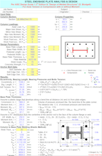
The program incorporates numerous 'comment boxes' throughout its interface, providing a wealth of information such as explanations of input or output items, equations used, and data tables. The presence of a 'comment box' is indicated by a 'red triangle' in the upper right-hand corner of a cell, with the content easily accessible by moving the mouse pointer to the desired cell.
-
Plate bending is calculated considering both plate bearing stress and anchor bolt tension. The effective plate width used for anchor bolt tension calculations is determined by the minimum of two values: (m-EDX) or (B-2EDY)/(2(NY-1)), along with additional considerations based on the number of bolts (NY).
-
It is recommended to use tp min = max(m/4 or n/4) to ensure a valid assumption of a rigid base plate.
-
Notably, this program does not cover predominantly high cycle fatigue or impact loads.
Calculation Preview
Full download access to any calculation is available to users with a paid or awarded subscription (XLC Pro).
Subscriptions are free to contributors to the site, alternatively they can be purchased.
Click here for information on subscriptions.


