MOVLOADS.xls

Description
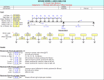
"MOVLOADS" is a spreadsheet program written in MS-Excel for the purpose of analysis of simple-span members subjected to from one (1) up to eight (8) moving wheel loads with up to seven (7) wheel spacings. Specifically, the maximum moment and location from the left end of the member and wheel postioning, the maximum end shears, the maximum deflection, and the maximum center support reaction for two (2) adjacent simple-span members are calculated.
This program is a workbook consisting of two (2) worksheets, described as follows:
Worksheet Name
Doc
Moving Loads
Program Assumptions and Limitations:
1. The following references were used in the development of this program (see below):
a. "Modern Formulas for Statics and Dynamics, A Stress-and-Strain Approach" by Walter D. Pilkey and Pin Yu Chang, McGraw-Hill Book Company (1978), pages 11 to 21.
b. AISC 9th Edition Allowable Stress (ASD) Manual (1989), pages 2-298 and 2-310.
2. This program uses the three (3) following assumptions as a basis for analysis:
a. Beams must be of constant cross section (E and I are constant for entire span length).
b. Deflections must not significantly alter the geometry of the problem.
c. Stress must remain within the "elastic" region.
3. To determine the value of the maximum moment and location from the left end of the left span for either only one (1) or two (2) wheel loads, those values are calculated directly by formulas.
4. To determine the value of the maximum moment and location from the left end of the left span for three (3) up to eight (8) wheel loads, the group of wheel loads is positioned with wheel load P1 situated directly over the left support. Then the group is moved to the right in 1/200*span increments, and the left and right reactions as well as the moments under each of the wheel loads are calculated. In moving the group of wheel loads incrementally from left to right, any wheels that would drop off of the span are done so. Then this entire procedure is mirrored for the opposite direction, from right to left.
Calculation Preview
Full download access to any calculation is available to users with a paid or awarded subscription (XLC Pro).
Subscriptions are free to contributors to the site, alternatively they can be purchased.
Click here for information on subscriptions.
Please include negative bending moment values for two trucks of same configuration but with variable headway distance between them.
Thank you
Thus, I added the user input data validation to restrict the input values of the wheel loads to values greater than 0.
This workbook is now version 1.2.
I also added some input data validation to restrict the input value of the Right Span (L2) to always be <= the Left Span (L1). This because the maximum moment, shear, and deflection calculations are only performed for the Left Span (L1). The only purpose of the Right Span (L2) is for determining the maximum column reaction at the center support between the two (2) simple span beams.
Finally, I added a "CAUTION" message off of the calculation page to the right and a pop up message on the calculation page to alert the user that when the sum of the wheel spacings >= the Left Span (L1), then user must input all other possible groupings of wheel loads/spacings that will fit on the Left Span (L1) to assure that the maximum moment has been determined. The only exception is the case for all equal wheel loads with all equal wheel spacings.


