BOEF.xls

Description
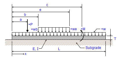
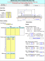
"BOEF" is a spreadsheet program written in MS-Excel for the purpose of analysis a finite length beam with free ends supported continuously on an elastic foundation. This program is ideally suited for analyzing a soil supported beam, a combined footing, or a strip of a slab or a mat. Specifically, the beam shear, moment, deflection, and soil bearing
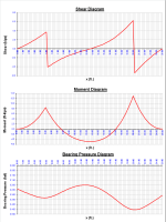
pressure are calculated for 100 equal beam segments, as well as the maximum values. Plots of both the shear, moment, and soil bearing pressure diagrams are produced, as well as a tabulation of the shear, moment, deflection, and bearing pressure for the beam.
This program is a workbook consisting of three (3) worksheets, described as follows:
Doc - documentation sheet
Beam on Elastic Fdn. (English) - Beam on elastic foundation analysis (English units)
Beam on Elastic Fdn. (metric) - Beam on elastic foundation analysis (metric units)
Program Assumptions and Limitations:
- The following reference was used in the development of this program (see below):
"Formulas for Stress and Strain" - Fifth Edition
by Raymond R. Roark and Warren C. Young, McGraw-Hill Book Company (1975), pages 128 to 146. - This program uses the equations for a "finite-length" beam in the analysis. This usually gives very similar to exact results for a "semi-infinite" beam which has had end-corrections applied to "force" the moment and shear values to be equal to zero at the ends. (Note: a "semi-infinite" beam is defined as one that has a b*L value > 6.)
- This program uses the five (5) additional following assumptions as a basis for analysis:
a. Beam must be of constant cross section (E and I are constant for entire length, L).
b. Beam must have both ends "free". ("Pinned" or "fixed" ends are not permitted.)
c. Elastic support medium (soil) has a constant modulus of subgrade, K, along entire length of beam.
d. Applied loads are located in the center of the width, B, of the beam and act along a centroidal line of the beam-soil contact area.
e. Bearing pressure is linearly proportional to the deflection, and varies as a function of subgrade modulus, K. - This program can handle up to twelve (12) concentrated (point) loads, a full uniformly distributed load with up to six (6) additional full or partial uniformly distributed loads, and up to four (4) externally applied moments.
- Beam self-weight is NOT automatically included in the program analysis, but may be accounted for as a full uniformly distributed applied load. Beam self-weight will only affect the deflection and bearing pressure, and not the moment or shear.
- This program will calculate the maximum positive and negative shears, the maximum positive and negative moments, the maximum negative deflection, and the maximum soil bearing pressure. The calculated values for the maximum shears, maximum moments, deflection, and bearing pressure are determined from dividing the beam into 100 equal segments with 101 points, and including all of the point load and applied moment locations as well.
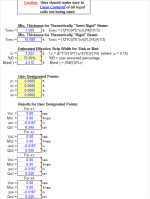
- The user is given the ability to input four (4) specific locations from the left end of the beam to calculate the shear, moment, deflection, and bearing pressure.
- The plots of the shear, moment, and bearing pressure diagrams as well as the displayed tabulation of shear, moment, deflection, and bearing pressure are based on the beam being divided up into 100 equal segments with 101 points.
- This program contains numerous “comment boxes” which contain a wide variety of information including explanations of input or output items, equations used, data tables, etc. (Note: presence of a “comment box” is denoted by a “red triangle” in the upper right-hand corner of a cell. Merely move the mouse pointer to the desired cell to view the contents of that particular "comment box".)
Calculation Reference
Beam Analysis
Roark's Formulas for Stress and Strain
AISC
Calculation Preview
Full download access to any calculation is available to users with a paid or awarded subscription (XLC Pro).
Subscriptions are free to contributors to the site, alternatively they can be purchased.
Click here for information on subscriptions.
You cannot compare a beam supported only at both ends with a beam continuously supported on an elastic medium. Yes, as we all know, the deflection is proportional to the cross section moment of inertia for a beam supported only at both ends, but that is definitely not the case for a continuously supported beam. For a beam on elastic foundation, the beam stiffness and the stiffness of the supporting elastic medium work together to determine how “rigid” or “flexible” the entire system is.
In your example problems, the less thick beam is already “semi-rigid” while the thicker beam is “theoretically rigid”. Once a beam/support system, is at least relatively rigid, then the applied loads are distributed basically linearly, as they would absolutely be in a “theoretically rigid” beam/support system. Thus, increasing the thickness of the beam would not have much effect on the deflection and bearing pressure. You should also remember to account for the difference in self weights when changing the thickness of the beam or slab/mat strip, as the thicker beam would result in a slightly larger defection and bearing pressure. However, increasing the thickness of the beam would obviously increase the shear capacity and lessen the reinforcing requirements for an assumed concrete cross section.
In any beam on elastic foundation analysis, I always pay particular attention to the resulting bearing pressure diagram. Linearity of the diagram is the dead giveaway of how rigid the particular beam/support system actually is.
Finally, a very important part of any beam on elastic foundation analysis, when used for analyzing a strip of a slab or mat, is the actual strip width that is input to be used in the analysis. Off of the main calculation page to the right, there is some suggested criteria that I present to help keep you from being either way too conservative or unconservative in the analysis. Increasing the slab or mat thickness would allow for an increase in the assumed strip width to be used in the analysis.
I hope this helps.
Alex
Why don't you [email me](/404/) and I'll make direct contact to will take a look at it for you.
While it's possible that there could be an issue, this spreadsheet has been used by countless people around the world for several years and I've never heard of an issue like the one that you are having. Of course, there is always a first time for everything, as the saying goes.
Alex
Thanks, Filename [BOEF.xls](/images/fbfiles/files/BOEF.xls), size 3972608
It was just brought to my attention that in the calculations for adjusting the subgrade modulus, in cell M65 where the spreadsheet was computing the final adjustment for a rectangular configuration the program logic was using the maximum of prior calculated values between sand or clay, instead of using the specific prior calculated value for either sand or clay. I have made the necessary correction in the program logic in cell M65 to select the value for whichever soil type was selected.
To summarize, what these calculations do for adjusting the subgrade modulus is first take the given k1 value from the geotechnical plate load test for the given plate width, B1, and then based on the soil type, sand or clay, convert it to a value reflecting a square footprint of BxB, where B is the assumed foundation or mat strip width. Then, the value adjusted for BxB is adjusted once again to reflect the actual footprint, LxB, where L is the input length and B is the assumed width.
As stated in the calculations and from the designated references, the adjustment equations deteriorate when the ratio of B/B1 > 3, and at that point a recommendation from the geotechnical consultant is advised.
The current version of this workbook is now version 1.6
First, off of the main calculation page to the right and below, I have added the ability to convert a given subgrade modulus (k) value derived from a geotechnical plate load test to what would be more applicable for the full size footing or strip of mat that is being analyzed. The references used are listed above the calculations. There is a noted limitation to this adjustment in the subgrade modulus, and it is always advised to consult the geotechnical engineer on the project for advice and recommendation on this subject.
Second, I also added the minimum soil bearing pressure and the percent bearing area resulting from the analysis. This, along with the additional comment boxes that I've added, should help the user determine the applicability and validity of a particular analysis using this spreadsheet.
For those of you who may not have ever tried or used this spreadsheet before, you might want to give it a try and become familiar with its capabilities. Sometimes we don't have the time (due to schedule) nor the need (preliminary engineering) for a more sophisticated FEM analysis. If this spreadsheet is used wisely and within its limitations, it will give you very acceptable results, efficiently. Plus, and maybe most importantly, it can help you understand the effects of a flexible vs. a rigid foundation/soil system, and give you quick insight on the thickness to use for a particular footing or mat when relative rigidity has been "casually" assumed initially in analysis, as is often done. Paying close attention to the plotted bearing pressure diagram will help you see just how flexible or rigid the footing or mat really is. When a "semi-rigid" to "rigid" condition is desired, you will be striving for a relatively linear distribution for the bearing pressure diagram.
The current version of this workbook is now version 1.5.
To help clarify the use of the "BOEF.xls" program, let me demonstrate with a simple example problem and compare results with my "FOOTINGS.xls" program.
In the "BOEF" workbook (English units worksheet) use the following input:
L = 8, B = 3, T = 2.25, E = 3600, K = 100, no full uniform or distributed loads, for point load a = 4 and P = 40, and for concentrated moment c= 4 and M = -70.
Now in the "FOOTINGS" workbook (8 net pier loads worksheet) use the following input: L = 8, B = 3, T = 2.25, assume soil and concrete unit weights = 0, Q = 0, pier is concentric on footing base, Load Pz = -40, and My = 70.
Per "FOOTINGS" program, results are:
pressures P1 = P2 = 3.951, and P3 = P4 = 0, with 84.38% of footing length in bearing.
Per "BOEF" program, results are:
maximum pressure = 3.840, with about 88% of footing length in bearing.
From these results, you see that even though the "BOEF" program solution depicts soil in tension (not really possible), the error in brearing pressure is still less than 3%. What I believe this says that as long as the the vast majortiy of the footing base (say 85%) is in bearing the "BOEF" program will still give very acceptable results.
Sorry for the "long winded" reply, but I thought this simple example would help.
Alex
No, there really is no error as far as the solution used per "Formulas for Stress and Strain" by Raymond Roark is concerned. Keep in mind that this solution has its limitations and there are no soil "springs", and as we all know the soil cannot take tension, only bearing. When you see "negative" bearing pressure results at the ends of the beam, footing, mat, mat strip, etc. it's a matter of proper interpretation. What this is telling you is that you really are way too flexible and not getting much distribution of the load, and thus you should increase the thickness. When you do increase the thickness, you will see that soil tension problem go away. This workbook is a GREAT tool for the structural engineer to quickly determine just how rigid or flexible the particular element is. Way too often the engineer, for simplicity sake, blindly assumes full theoretical rigidity in an analysis, where that may not be the case at all. Also, this workbook will help the engineer determine the shear and moment for combined footings (with say 2 piers) that can be used in the concrete design.
In closing, this workbook is certainly not intended nor capable of being a subsitute for a much more sophisticated analysis such as FEM or finite differences. But as I said, when it is used properly, the results and limitations are understood and properly interpreted, it can be a very efficient and timely tool.
Alex
I also expanded on and added some input data validation and comment boxes to help further clarify the usage and application of this program.
The program breaks up the beam length into 100 segments for the purpose of determining the maximum shears, moments, deflection, and bearing pressure, as well as for the purpose of plotting the graphs. The 100 segments will get you real close, but will not always assure that the exact maximums are captured. Thus to help improve the accuracy, the program also performs the calculations for 4 user designated x-distance locations from the left end, as well as the x-distance locations of the various loads. Cell IS132 was referring to the x-distance for Point Load #8. Since there was no value in cell B340, the value in cell IS132 for the x-distance became = 0. However, 100 segment graphed results were not affected by this "typo-error".
This spreadsheet is based on the well known and reputed Roark reference, as cited in the "DOC" worksheet. Depending on the degree of flexiblity of the beam or slab/mat strip, as well as the nature of the applied loads, the solution for bearing pressures may show tension (uplift) at the ends. While we all know that soil cannot resist tension, what this does represent is that your situation is too flexible to distribute out the loads. This spreadsheet is not intended to be a replacement for a finite element model (FEM) analysis, and the solution/formulas do not directly involve the use of "springs". However, sometimes we either don't have the time or it may not be worth the extra effort involved to do an FEM analysis. This spreadsheet, when used and interpreted properly, can be a very quick and powerful tool for helping the engineer determine just how flexible or rigid a particular beam or slab/mat strip really is (or needs to be), and thus how much load distribution is actually occurring. Engineers often blatantly assume "rigidity" in their analyses. This spreadsheet can help either prove or disprove those assumptions.
Hope this helps.
Alex
For slab on grade analysis/design, you could and probably should use my "GRDSLAB.xls" workbook. I use the "BOEF.xls" workbook mainly for analyzing combined footings and strips of mat foundations.
Alex
Assuming a rigid beam/footing will usually over estimate the flexure (bending), so your rigid assumption for flexure is most always conservative as long as you don't over estimate the effective strip width. Where you can get into trouble is by assuming a rigid condition and if what you have is actually quite flexible, the maximum soil bearing pressure will be under estimated. For a very rigid beam/footing the bearing pressure diagram will be linear, while for a very flexible beam/footing the bearing pressure diagram will be "bulbed" directly under applied concentrated (point) loads. Keep in mind the scaling constraints of the MS-Excel plot for bearing pressure, when examining plots that should be a relatively straight line for a rigid condition.
Alex
One comment. Are the units for the Minimum thicknesses supposed to be in inches instead of feet? The minimum thicknesses would be ridiculously large if it was in feet.


