Pin and Lug.xls

Description
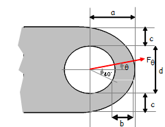
When calculating the proof and ultimate strength of obliquely loaded lugs, it's essential to consider the forces acting on the lug and their respective components. The forces can be divided into axial and transverse components to simplify the analysis. Here's a step-by-step process to calculate the proof and ultimate strength of obliquely loaded lugs:
-
Identify the applied load: Determine the magnitude (P) and the direction (θ) of the applied force acting on the lug.
-
Resolve the applied load into components: Divide the applied force into axial (P_axial) and transverse (P_transverse) components.
P_axial = P * cos(θ) P_transverse = P * sin(θ)
-
Determine the lug geometry: Define the lug's dimensions, such as hole diameter (d), edge distance (e), and lug thickness (t).
-
Calculate the bearing area: Compute the bearing area (A_bearing) between the lug and the pin as follows:
A_bearing = d * t
-
Determine the allowable bearing stress: Based on the material properties of the lug and the safety factor, find the allowable bearing stress (?_bearing_allowable) for both proof and ultimate conditions.
-
Calculate the proof and ultimate bearing capacities: Compute the proof and ultimate bearing capacities (P_bearing_proof, P_bearing_ultimate) as follows:
P_bearing_proof = A_bearing * σ_bearing_allowable_proof P_bearing_ultimate = A_bearing * σ_bearing_allowable_ultimate
-
Determine the allowable shear stress: Based on the material properties of the lug and the safety factor, find the allowable shear stress (τ_shear_allowable) for both proof and ultimate conditions.
-
Calculate the proof and ultimate shear capacities: Compute the proof and ultimate shear capacities (P_shear_proof, P_shear_ultimate) using the following formula:
P_shear_proof = A_bearing * τ_shear_allowable_proof P_shear_ultimate = A_bearing * τ_shear_allowable_ultimate
-
Calculate the combined proof and ultimate capacities: Since the axial and transverse components of the applied force act simultaneously, use the interaction equation to find the combined proof and ultimate capacities (P_proof, P_ultimate):
P_proof = (P_axial / P_bearing_proof) + (P_transverse / P_shear_proof) P_ultimate = (P_axial / P_bearing_ultimate) + (P_transverse / P_shear_ultimate)
-
Compare the applied load to the capacities: Compare the applied load (P) to the combined proof and ultimate capacities (P_proof, P_ultimate) to ensure that the lug can safely withstand the oblique load. If the applied load exceeds the capacities, consider modifying the lug's design or material properties.
In summary, calculating the proof and ultimate strength of obliquely loaded lugs involves resolving the applied load into axial and transverse components, determining the lug geometry, calculating the bearing and shear capacities for both proof and ultimate conditions, and comparing the applied load to the combined capacities. Ensuring that the lug can safely withstand the oblique load is crucial for maintaining the structural integrity of the connection.
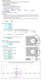
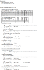
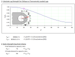
Purpose of calculation: Calculate the proof and ultimate strength of obliquely loaded lugs.
This calculation has been extended to also consider fatugue strength.
Calculation Reference: Traditional UK railway method.
Calculation Validation: This calculation requires validation.
Design Tips:
- It is normal to choose a pin size 6mm larger than required to allow for off centre drilling etc.
- You may want to consider the use of a replaceable bush to increase the wear life of the lug.
3)You may also have to consider fatigue life.Calculation Reference
Peterson's Stress Concentration
Juvinal Design
Calculation Preview
Full download access to any calculation is available to users with a paid or awarded subscription (XLC Pro).
Subscriptions are free to contributors to the site, alternatively they can be purchased.
Click here for information on subscriptions.


