Double Wall Thermal Stress
Description
This spreadsheet calculates analytical temperatures and stresses in a double wall cylinder for the case of a fixed inner wall temperature and temperature dependent forced convection to some ambient temperature on the outer surface, combined with an internal pressure.
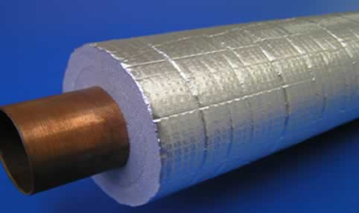
Double walled cylinders occur in many instances, such as bimettalic cylinders, outer insulated pipes or shells with an inner lining designed to protect the outer shell from high temperatures.
This spreadsheet calculates the steady state radial temperature distribution through the wall thicknesses for the case of the inner surface fixed at some constant temperature whilst forced convection to some ambient temperature is applied
to the outer surface. To allow non-linear effects, such as natural convection and radiation, the spreadsheet allows a temperature dependent heat transfer coefficient (or film coefficient) to be defined for forced convection. The spreadsheet
adopts an iterative method to solve for this non-linear boundary condition that uses the Goal Seek function of Excel to seek convergence.
With temperatures calculated through the wall thicknesses, the spreadsheet also calculates stresses through the walls. Stresses and displacements are calculated on the basis of either generalized plane strain or plane stress conditions.
The former assumes that the axial strain is constant across the section and represents stresses in infinitely long cylinders. The latter case of plane stress assumes zero axial stress and represents stresses in a thin disc or, approximately,
the stress distribution at a free end of a cylindrical wall. For completeness, an internal pressure can be applied to the double walled cylinder to add to the thermal stresses produced.
The method could also be used for a single walled cylinder by simply imposing the same material properties for both cylinder walls and dividing the wall thickness. Note that units of mm or ft can be selected, however these are for convenience only. No conversion of units is made in the calculation as units are assumed to be consistent throughout. Results from an example show close agreement with results using finite element methods with a relatively fine mesh.
Input
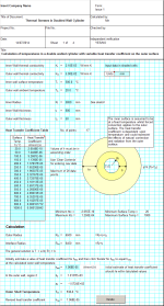
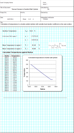
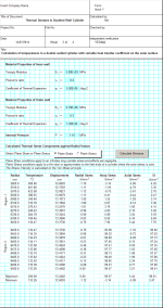
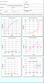
The spreadsheet 'Calculation' is separated into four standard calculation style pages that combines both input and output, where
Page 1 contains the input required to determine the steady state temperatures
Page 2 shows the calculated temperatures at 21 points through the two walls.
Page 3 contains the input required to determine the displacements and stresses through the two walls
Page 4 shows the displacement and stress results in graphical format.
Within page 1 of the calculation, forced convection on the outer surface is defined by a table of temperature dependent heat transfer coefficients (htc). If a constant htc is required then simply input one value at a temperature of say zero degrees. The maximum number of data points permitted is 20. Note that values of htc must be input in ascending order.
To facilitate the iteration process, an initial estimate of htc must be input for hest (cell N70). Clicking on the 'Iterate' button will begin the iteration process. This uses the calculated surface temperature of the outer cylinder using the initial estimate of the htc, and then calculates a revised htc by linear interpolation from within the table. Convergence is achieved when the calculated htc equates to the final calculated surface temperature.
Page 3 of the calculation requires the material properties used to calculate displacements and stresses. In addition an internal pressure can be defined for the inner radius of the double walled cylinder.
Calculated stresses are based upon the calculated temperature distribution and applied pressure such that :
The radial stress is equal to the negative value of internal pressure at the inner radius
The radial stress is zero at the outer radius
The radial stress is equivalent at the interface between the two cylinder walls
The displacement is equivalent at the interface between the two cylinder walls
For plane strain, axial strain is equal across both cylinder walls (but not necessarily zero)
For plane stress the axial stress is zero.
Select either Plane Strain or Plane Stress and then click on the button 'Calculate Stresses'. Calculated stresses are shown in graphical form in page 4 of the calculation.
Verification of the calculation is made by comparison with results from an Abaqus v6.13 finite element (FE) model using the same input as shown in the Calculation sheet.
Note that some discrepancies exist in the FE results due to mesh refinement and nodal extrapolation of the results from the element integration points. For instance, the radial stress is not exactly equal to the internal pressure at the inner radius, nor exactly zero at the outer radius. Similarly at the interface of the two regions the radial stress is not exactly equivalent, as required in theory. In general, however, there is close agreement between the FE results and theoretical results from the spreadsheet.
Calculation Reference
Thermal Analysis
Piping Thermal Calculations
Temperature Distribution in Pipes
Calculation Preview
Full download access to any calculation is available to users with a paid or awarded subscription (XLC Pro).
Subscriptions are free to contributors to the site, alternatively they can be purchased.
Click here for information on subscriptions.

