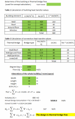
Determine if the building is thermal bridge free

Description
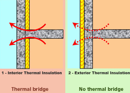
A thermal bridge, also called a cold bridge is a fundamental of heat transfer where a penetration of the insulation layer by a highly conductive or noninsulating material takes place in the separation between the interior (or conditioned space) and exterior environments of a building assembly (also known as the building enclosure, building envelope, or thermal envelope). Thermal bridging is created when materials that are poor thermal insulators come into contact, allowing heat to flow through the path of least thermal resistance (R-value; or a material's effectiveness in resisting the conduction of heat) created, although nearby layers of material separated by airspace allow little heat transfer. Insulation around a bridge is of little help in preventing heat loss or gain due to thermal bridging; the bridging has to be eliminated, rebuilt with a reduced cross-section or with materials that have better insulating properties, or with a section of material with low thermal conductivity installed between metal components to retard the passage of heat through a wall or window assembly, called a thermal break.
Calculation Reference
Thermal Analysis
Thermal Losses in Buildings
Thermal Bridge Design
A thermal bridge, also known as a thermal bypass or thermal bridging, refers to a localized area or component in a building's thermal envelope where heat transfer occurs more easily compared to the surrounding areas. It creates a path of higher heat flow, resulting in increased heat loss or gain and reduced energy efficiency.
Thermal bridges can occur in various forms, such as:
-
Structural thermal bridges: These are typically found in building elements that penetrate the insulation layer, such as concrete or steel columns, beams, or connections. These structural elements have higher thermal conductivity than the surrounding insulation, allowing heat to bypass the insulation and flow more easily.
-
Geometric thermal bridges: These are caused by irregular shapes or changes in the building envelope, such as corners, wall-floor junctions, or roof-wall junctions. These areas often have a higher surface area-to-volume ratio, leading to increased heat transfer compared to the surrounding areas.
Determining heat loss at a thermal bridge using fundamental hand calculations involves applying simplified equations and assumptions. While more accurate results can be obtained using specialized software or numerical modeling, hand calculations provide a quick estimate of the heat loss. Here are the fundamental steps involved:
-
Identify the thermal bridge: Identify the location and geometry of the thermal bridge in the building envelope.
-
Determine the thermal conductivity: Determine the thermal conductivity (k) of the materials involved in the thermal bridge. This value represents the material's ability to conduct heat.
-
Calculate the thermal resistance: Calculate the thermal resistance (R) of the thermal bridge using the equation:
R = L / (k * A)
Where: R is the thermal resistance (in m²K/W), L is the length of the thermal bridge (in meters), k is the thermal conductivity of the material (in W/mK), A is the cross-sectional area of the thermal bridge (in square meters).
-
Determine the temperature difference: Determine the temperature difference (ΔT) between the indoor and outdoor environments.
-
Calculate the heat flow: Calculate the heat flow (Q) through the thermal bridge using the equation:
Q = (ΔT) / R
Where: Q is the heat flow (in watts).
This calculation assumes steady-state conditions and neglects factors such as convection and radiation. It also assumes linear heat flow through the thermal bridge and does not consider the complex three-dimensional heat transfer that may occur in actual structures. Therefore, it provides a rough estimate of the heat loss and is best used for preliminary evaluations or comparative purposes.
It's important to note that for accurate calculations and comprehensive analysis of thermal bridges, using specialized software or consulting building energy professionals is recommended. These tools and experts can consider additional factors, such as surface emissivity, convective heat transfer, and more detailed geometries to provide more precise heat loss estimations.
Calculation Preview
Full download access to any calculation is available to users with a paid or awarded subscription (XLC Pro).
Subscriptions are free to contributors to the site, alternatively they can be purchased.
Click here for information on subscriptions.


