SECTPROP.xls

Description
"SECTPROP" is a spreadsheet program written in MS-Excel for the purpose of calculating section properties. Two methods of input data are provided, either by adding of deleting "shapes" or by defining a polygon by a series of "points". Specifically, the centroid location and total area are determined, as well as the centroidal and principal axes moments of inertia, radii of gyration, and rotation angle.
This program is a workbook consisting of three (3) worksheets, described as follows:
- Doc
- Shapes
- Points
- Stress
Program Assumptions and Limitations:
1. This program will calculate the centroid location, total cross-sectional area, moments of inertia, and radii of gyration for the centroidal axes and the principal axes if applicable. The value of the rotation angle between the centroidal and principal axes is also calculated.
2. Units are any consistent set of units the user desires.
3. In the case of both calculation worksheets, the user should make sure to either clear the contents of all spreadsheet cells that are not used for input or those cell values should be input = 0.
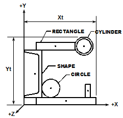
4. Using the Shapes worksheet, the origin X-axis MUST BE located at the lowest (bottom) point of the total section. The overall height of the total section (in Y-direction) MUST BE correctly input as well.
5. In using the Shapes worksheet, the origin Y-axis MUST BE located at the left most point of the total section. The overall width of the total section (in X-direction) MUST BE correctly input as well.
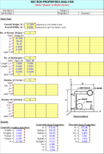
6. Using the Shapes worksheet, there is input for the number of rectangles, circles, cylinders, and symmetrical shapes with known properties to be either added and/or deleted in order to model a particular section. For rectangles, circles, and cylinders, there is input for applicable dimensions as well as the location of the centroid from the assumed origin axes. For shapes with "known" properties, there is input for the self area, self moments of inertia, and location of the centroid from the assumed origin axes.
7. Using the Shapes worksheet, any "known" shapes that are input should usually be at least singularly symmetric (Ixy=0), except for the special case where the entire section to be modeled is at least singularly symmetric. For example, a "known" angle shape should be modeled as two rectangles, unless there is a "matching" angle to create overall symmetry about at least one axis.
8. Using the Shapes worksheet, when a total section is made up of ONLY rectangles, an approximate value of the torsional constant, 'J', is displayed at the bottom of the worksheet (cells A51 and B51) under thecomposite section properties calculations. (Note: cells A48, A49, B48, and B49 are "unlocked" so that the resulting value of 'J' may be manually typed in for print out if desired.)
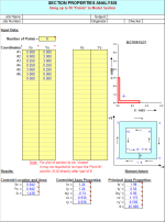
9. Using the Points worksheet, the modeled section can be any polygon defined by up to 50 connectable points, each with its own set of X,Y coordinates (3 points are a minimum). The number of points is the actual total number of different points required to define the polygon. While it is NOT required to redefine the start point to "define" the polygon (as the program will automatically "close" the polygon after the end point has been defined), in some cases it may be required to re-enter the coordinates of starting Point #1 directtly after the last defined point coordinates, so that the plot of the section will appear "closed".
10. Using the Points worksheet, coordinates of each point are input, proceeding in a CLOCKWISE direction for (positive) area to be added, and then in a COUNTER-CLOCKWISE direction for (negative) area to be deleted.(See "Nomenclature" illustration for example.)
11. Using the Points worksheet, the origin MUST BE located so that the entire section is in the positive quadrant. Negative coordinates ARE NOT acceptable.
12. This program contains numerous “comment boxes” which contain a wide variety of information including explanations of input or output items, equations used, data tables, etc. (Note: presence of a “comment box” is denoted by a “red triangle” in the upper right-hand corner of a cell. Merely move the mouse pointer to the desired cell to view the contents of that particular "comment box".)
Calculation Reference
AISC
Calculation Preview
Full download access to any calculation is available to users with a paid or awarded subscription (XLC Pro).
Subscriptions are free to contributors to the site, alternatively they can be purchased.
Click here for information on subscriptions.
Comments: 10
×
12 years ago
It was brought to my attention that in the "Shapes" worksheet of the "SECTPROP.xls" spreadsheet workbook, if the user was adding multiple cylinders the program was inadvertently only referencing the values for the first cylinder that was input when determining the composite section properties. I have made the necessary cell referencing corrections pertaining to only the cylinders. The other shapes were fine.
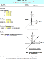
While I was at it, I decided to expand the capability of the "Stress" worksheet in this workbook. Before, the worksheet only allowed the user to determine the combined stress at one point within the cross section at a time. I have expanded that now so that the worksheet can calculate and display the stress results for up to six (6) points at one time. I also added a cautionary note to remind the user to make sure that the points to be investigated are actually within the given cross section.
This workbook is now version 2.5.
15 years ago
Adel Al-baba You can have access to the full repository for free if you contribute a calculation of your own. See details here /earn-your-subscription/
15 years ago
guys i want this sheet for educational issues , as i'm working on a steel structure project for my study in steel design course , please help and i'll be thankful
Eng.Adel Al-baba
Eng.Adel Al-baba
17 years ago
John,
When I think about it, if I had of reversed the positive (+) direction of the Z axis shown in the illustration, then it would not have seemed odd to you, and maybe others. I'm just "old school", stuck on the traditional x-y-z orthogonal axis setup, with the Z axis out of the page/screen.
Alex
When I think about it, if I had of reversed the positive (+) direction of the Z axis shown in the illustration, then it would not have seemed odd to you, and maybe others. I'm just "old school", stuck on the traditional x-y-z orthogonal axis setup, with the Z axis out of the page/screen.
Alex
17 years ago
There is no confusion in the use of your convention and the calculation states whether its in tension or compression quite clearly. It just seems odd to my way of thinking - but then I am a mechanical engineer not a structural engineer. Thanks for your quick response.
17 years ago
John,
In the "Stress" worksheet of the "SECTPROP.xls" workbook, the axial force (Pz) and moments (Mx and My) are applied via strict "Right-Hand-Rule" notation.
For the axial force (Pz), a positive value (+) is denoted as tension, because +Z is going away from the member cross-section. I know that having a resultant section tension stress displayed as negative (-) and
a compression stress displayed as positive (+) seems contrary. However, I was trying to keep compression stress as positive (+) and tension stress as negative (-) because that's the convention that most of the software packages that I've used seem to follow.
Initially, sign convention is important/significant to assure that the force and moments are applied correctly, and that subsequently the stresses are combined properly. To me, the sign convention used on the resultant stress at any point in the cross section is not as important as knowing whether that stress is compression or tension. For that matter, I could have eliminated the use of a sign altogether on the resultant stress and merely indicated either whether it is compression or tension.
If you're not comfortable with my approach on this, then all you have to do is as follows:
1. For - = compression, + = tension stress results Revise the signs used in combined stress formula to +P, -My, and +Mx (all opposite to how I have them currently as -P, +My, and -Mx)
2. Swap the words "compression" and "tension" in the logic in cell C30.
Well now you've heard my rationale, now matter how strong/weak it is, for why I chose to do it the way I did. I'm not totally opposed to changing it, but since you're the only person who has raised this question thus far, I'll hold off until/unless I get some similar feedback from folks.
Alex
17 years ago
Hi Alex just a quick query. On the 'Stress' worksheet why is a tensile stress a negative value? It seems to conflict with the note in B17.
I am developing a new section calculation for sections defined by lines and I would like to keep it as consistent as possible with your one so they can be used together. Once again thanks for all your hard work.
I am developing a new section calculation for sections defined by lines and I would like to keep it as consistent as possible with your one so they can be used together. Once again thanks for all your hard work.
17 years ago
A couple of glitches were discovered in the "Points" worksheet of the "SECTPROP.xls" workbook. There was a range/column of cells in the calculations, M29 through M38 which had an invalid cell reference (#REF!) in each of them. This problem would have shown up for points #26 through #35. Also, the series data to draw the plot omitted the 'yo' coordinate for a group of points, thus even if the other problem had not existed, all of the points would not have shown up in the plot. The necessary corrections have been made, and the workbook is now version 2.4.


Also, in the "Points" worksheet where a plot of the cross section is created, I revised the procedure for obtaining/maintaining a more correct aspect ratio for the plot. Off of the calculation page and to the upper right, the user now inputs a value which is termed as "Axes Lengths Ratio"......the ratio of the actual on-screen measured lengths of the X and Y axes. This should keep the plot looking more to correct scale than has been in the past.
The current version of this workbook is now version 2.6.