Seismic Wave Propagation in Ductile Iron Pipe

Description
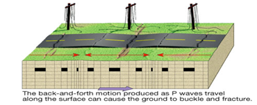
This spreadsheet calculates the axial joint displacement of unrestrained ductile iron pipes or longitudinal stresses in restrained joint ductile iron pipes due to seismic wave propagation in the event of an earthquake.
Calculation Reference
Seismic Assessment
ASCE 7
AWWA American Water Works Association
Seismic assessment and design of ductile iron pipe systems can be complex and requires thorough knowledge of engineering principles and relevant standards. ASCE 7 is a standard that provides minimum design loads for buildings and other structures. However, it does not specifically address ductile iron pipes. For ductile iron pipes, AWWA standards, such as AWWA C150, AWWA C151, and AWWA C600, provide guidance on design, manufacturing, and installation practices.
To estimate axial joint displacement in unrestrained ductile iron pipes or longitudinal stresses in restrained joint ductile iron pipes due to seismic wave propagation, you will need to consider multiple factors, including:
-
Site-specific seismic hazard data: Determine the seismic hazard at the site, typically expressed as peak ground acceleration (PGA) or spectral acceleration (Sa). Local seismic hazard maps or geological surveys can provide this information.
-
Pipe properties: Gather information on the ductile iron pipe, such as diameter, wall thickness, material properties (e.g., modulus of elasticity, yield strength), and joint type (restrained or unrestrained).
-
Soil properties: Evaluate soil conditions at the site, including soil type, density, and shear wave velocity. These factors can influence the response of buried pipelines during an earthquake.
-
Pipe-soil interaction: Consider the interaction between the pipe and surrounding soil, which can influence the pipe's response to seismic waves. The Housner model and the Newmark-Hall method are commonly used methods for estimating pipe-soil interaction.
To calculate axial joint displacement or longitudinal stresses in ductile iron pipes due to seismic wave propagation, you can use the following general procedure:
-
Determine the design seismic force acting on the pipe based on site-specific seismic hazard data and relevant standards.
-
Perform a dynamic analysis of the pipeline system, taking into account pipe properties, soil properties, and pipe-soil interaction. This analysis may require the use of specialized software or analytical methods, such as finite element analysis or simplified analytical models.
-
Evaluate the axial joint displacement or longitudinal stress in the pipe due to the seismic forces. Compare these values to the allowable limits specified in the relevant standards, such as AWWA C150 or AWWA C151.
Keep in mind that this is a simplified overview of the process, and a qualified engineer with experience in seismic design should be consulted to ensure a comprehensive analysis.
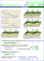
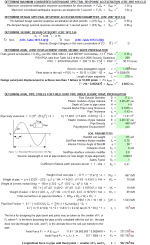
Calculation Preview
Full download access to any calculation is available to users with a paid or awarded subscription (XLC Pro).
Subscriptions are free to contributors to the site, alternatively they can be purchased.
Click here for information on subscriptions.


