PIPE THICKNESS CALCULATION

Description
Piping Thickness calculation as per ASME B31.1
ASME B31.1 is the Power Piping code that covers the design, fabrication, installation, inspection, and testing of piping systems typically found in electric power generating stations, industrial and institutional plants, and district heating systems. One of the key aspects of designing a piping system is determining the required pipe wall thickness to withstand internal pressure.
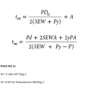
To calculate the required pipe wall thickness according to ASME B31.1, you can use the following formula, which is derived from the Barlow's formula:
t = (P * D) / (2 * S * E + P * Y)
where:
- t is the minimum required wall thickness (mm or in)
- P is the internal design pressure (MPa or psi)
- D is the outside diameter of the pipe (mm or in)
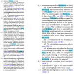
- S is the allowable stress for the pipe material at the design temperature (MPa or psi), which can be found in ASME B31.1, Table A-1 or other relevant material specifications
- E is the longitudinal weld joint quality factor (dimensionless), typically equal to 1 for seamless pipes or based on the type of welding procedure for welded pipes, as specified in ASME B31.1, Table A-1A
- Y is the coefficient that accounts for material strength variation in the hoop and axial directions (dimensionless), which can be found in ASME B31.1, Table A-1
To calculate the minimum required wall thickness (t) using the ASME B31.1 formula, follow these steps:
- Determine the internal design pressure (P) based on the system's operating pressure and any applicable safety factors or pressure allowances.
- Measure or obtain the outside diameter (D) of the pipe.
- Determine the allowable stress (S) for the pipe material at the design temperature, which can be found in ASME B31.1, Table A-1 or other relevant material specifications.
- Determine the longitudinal weld joint quality factor (E) based on the pipe's manufacturing process, as specified in ASME B31.1, Table A-1A.
- Determine the coefficient Y based on the pipe material, which can be found in ASME B31.1, Table A-1.
- Plug the values for P, D, S, E, and Y into the formula and calculate the minimum required wall thickness (t).
Keep in mind that the calculated minimum wall thickness may need to be increased for factors not considered in the formula, such as corrosion, erosion, or mechanical loads. Additionally, pipe thicknesses are typically available in standard sizes, so the actual pipe thickness used should be equal to or greater than the calculated minimum wall thickness.
Calculation Preview
Full download access to any calculation is available to users with a paid or awarded subscription (XLC Pro).
Subscriptions are free to contributors to the site, alternatively they can be purchased.
Click here for information on subscriptions.


