WALLPRES.xls
Description
'WALLPRES' --- WALL PRESSURE ANALYSIS
Program Description:
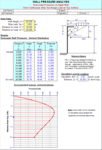
'WALLPRES' is a spreadsheet program written in MS-Excel for the purpose of determining the horizontal (lateral) pressures to be applied to walls from various types of loading including lateral earth pressure, hydrostatic pressure, as well as uniform, point, line, and strip surcharge loadings.
This program is a workbook consisting of five (5) worksheets, described as follows:
Doc - documentation sheet
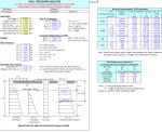
Wall Soil Pressures - Static horizontal soil pressure against wall
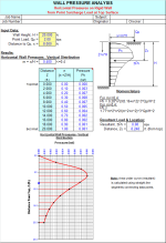
Wall Pressures from Point Load - Horizontal pressures on rigid wall from point surcharge load
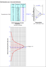
Wall Pressures from Line Load - Horizontal pressures on rigid wall from continuous strip surcharge load
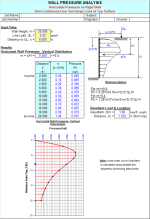
Wall Pressures from Strip Load - Horizontal pressures on rigid wall from continuous line surcharge load
Program Assumptions and Limitations:
1. This program is based on the following references:
a. NAVFAC DM-7.02 Manual - 'Foundations & Earth Structures' (1986)
b. NAVFAC DM-7.01 Manual - 'Soil Mechanics' (1986)
c. Army TM 5-818-1 / Air Force AFM 88-3, Chap. 7 (Oct. 1983) 'Soils and Geology Procedures for Foundation Design of Buildings and Other Structures'
d. 'Foundation Analysis and Design' (2nd Edition), by: Joseph E. Bowles McGraw-Hill, 1977
e. 'USS Steel Sheet Piling Design Manual' - updated and reprinted by FHWA with permission (July 1984)
f. 'Lateral Soil Pressure on Retaining Walls and Embedded Exterior Walls of Structures' Report U7-PROJ-S-RPT-STRU-6001, by: Sargent & Lundy, LLC (Feb. 26, 2009) for South Texas Project Units 3 & 4, Project No.: 12462-003
2. The resulting pressures obtained from the worksheets in this workbook can be used in the design of the stems of either cantilever or propped cantilever retaining walls, as well as for long walls of tanks and pits.
3. The equations used in the 'Wall Pressures from Point Load' and 'Wall Pressures from Line Load' worksheets are from References 'a' through 'e' above, utilizing original (1885) Boussinesq Equations modified to correlate with experimental test results. The Boussinesq equations assume the that wall is rigid and does not move, and that the wall is perfectly smooth (no shear stress between wall and soil). Thus, the equations overestimate the wall pressures for flexible walls by up to a factor of 2.
4. The equation used in the 'Wall Pressures from Strip Load' worksheet is from References 'd' and 'e' above. Again, this equation assumes that the wall is rigid (does not move), which overestimates the wall pressures for flexible walls by up to a factor of 2. Thus, the factor of 2 appears in the numerator of this version of the equation. Other references may cite this equation without the factor of 2, which would normally be more applicable for flexible walls which are able to move at top.
5. This program contains “comment boxes” which contain information including explanations of input items, etc. (Note: presence of a “comment box” is denoted by a “red triangle” in the upper right-hand corner of a cell. Merely move the mouse pointer to the desired cell to view the contents of that particular 'comment box'.)
Designing a retaining wall requires understanding the soil properties, loading conditions, and various design factors. Using the references you provided, I will give you an overview of the steps to design a retaining wall.
-
Site investigation and soil properties: Perform a thorough site investigation to gather information about the soil properties and geotechnical conditions. Use the guidelines provided in NAVFAC DM-7.01 Manual - 'Soil Mechanics' (1986) and Army TM 5-818-1 / Air Force AFM 88-3, Chap. 7 (Oct. 1983) 'Soils and Geology Procedures for Foundation Design of Buildings and Other Structures' to determine the soil properties, such as strength, stiffness, and permeability. Soil properties are crucial for retaining wall design, as they affect the lateral earth pressure, bearing capacity, and sliding resistance.
-
Retaining wall type and geometry: Select the appropriate retaining wall type (e.g., gravity, cantilever, sheet pile, anchored) based on the site conditions, required wall height, and aesthetic considerations. Determine the retaining wall geometry, including the wall height, thickness, and length. Refer to NAVFAC DM-7.02 Manual - 'Foundations & Earth Structures' (1986) for guidance on selecting the appropriate retaining wall type and geometry.
-
Lateral earth pressure: Calculate the lateral earth pressure acting on the retaining wall using the guidelines provided in 'Lateral Soil Pressure on Retaining Walls and Embedded Exterior Walls of Structures' Report U7-PROJ-S-RPT-STRU-6001, by: Sargent & Lundy, LLC (Feb. 26, 2009) for South Texas Project Units 3 & 4, Project No.: 12462-003. The lateral earth pressure depends on the soil properties, retaining wall geometry, and loading conditions (e.g., surcharge loads, water table).
-
Bearing capacity and sliding resistance: Evaluate the bearing capacity of the soil beneath the retaining wall using the methods described in 'Foundation Analysis and Design' (2nd Edition), by: Joseph E. Bowles McGraw-Hill, 1977. Calculate the sliding resistance of the retaining wall based on the soil properties and wall geometry.
-
Stability analysis: Perform a stability analysis for the retaining wall, considering factors such as overturning, sliding, and bearing capacity. Ensure that the retaining wall meets the required factors of safety for each stability criterion. NAVFAC DM-7.02 Manual - 'Foundations & Earth Structures' (1986) provides guidance on the stability analysis of retaining walls.
-
Sheet pile retaining walls: If you are designing a sheet pile retaining wall, refer to the 'USS Steel Sheet Piling Design Manual' - updated and reprinted by FHWA with permission (July 1984) for guidance on the design of steel sheet piles, including the selection of sheet pile sections, driving criteria, and connection details.
-
Retaining wall construction and drainage: Consider the construction method, materials, and equipment required to build the retaining wall. Plan for proper drainage behind the retaining wall to prevent hydrostatic pressure buildup, which can compromise the wall's stability.
In summary, designing a retaining wall involves understanding the soil properties, selecting the appropriate retaining wall type and geometry, calculating lateral earth pressures, evaluating bearing capacity and sliding resistance, and performing a stability analysis. The references you provided offer valuable guidance for each step of the design process, ensuring a safe and effective retaining wall design.
Calculation Preview
Full download access to any calculation is available to users with a paid or awarded subscription (XLC Pro).
Subscriptions are free to contributors to the site, alternatively they can be purchased.
Click here for information on subscriptions.

