Bearing Capacity in multi-layer soils

Description
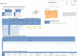
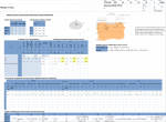
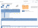
Calculation of bearing pressures to BS EN 1997-1 (EC7) and UKNA (Design Approach 1) for soils with more than one layer. Used in foundation design and for temporary works (crane outriggers etc). Four worksheets; Notes, Rectangular, Circular and Strip, for different loading patterns. Calculates bearing capacity and pressure for DA1 Combination 1 and Combination 2 and for servicability limit state. Requires user understanding of basic geotechnical terms.
This spreadsheet is for the calculation of bearing pressure in multi-layered soils using Design Approach 1 in EC7. An ability to interpret Gropund Investigation Reports and an understanding of drained and undrained conditions is assumed. There are three worksheets, one each for square and rectangular bases, circular bases and for strip footings.
Cells for user input are shaded light blueCells with output values are shaded light yellowCells without shading are not intended to be altered
The decimal separator is a comma ','
BS EN 1997-1 2004 A1 2013 Geotechnical Design General Rules
BS EN 1997-1 UKNA 2004 A1 2013 Geotechnical Design General Rules
Salgado R et al (2004) 69_Two-and-three-dimensional-bearing-capacity-of-foundations-in-clay
Tomlinson Foundation Design and Construction [7th ed]
The spreadsheet requires the factored actions from Combination 1 (loads factored by 1,35 and 1,5), from Combination 2 (loads factored by 1,0 and 1,3) and for Servicability Limit State
There is provision to add a surface unifiorm distributed surcharge, and in the case of rectangular/square and circular bases, a horizontal action and direction which can be used to emulate an appliied moment
These are copied from the UK National Annex and are not intended to be altered by the user
Enter the base dimensions. The effective length and effective breadth (taking into account any eccentricity) should be used.
For each layer, the geotechnical properties have to be stated.
Layer 0 is intended to be the weight of the soil above the formation. In the case of a working platform for plant, there is no Layer 0 and the thickness is zero
For layers 1 to N, add a description of the material to assist identification and the unit weight. For undrained conditions in clay enter either undrained shear strength and zero for internal angle of friction- not both. Sands and gravels use drained properties. If drained conditions are also needed for clays, copy the spreadsheet and enter the drained properties instead of undrained.
For each layer enter the thickness.
The spreadsheet calcuates the bearing pressure at the top of the layer below, using the spread angle entered. (Spread anges are a whole topic on their own; 45 degrees - used extensively - is most probably too high)
Bearing pressure and capacity are calculated for each of the three cases Design Approach 1 Combination 1, Design Approach 2 Combination 2 and Servicability
For ULS DA1/C1 and DA1/C2 the utilisation ratio of bearing pressure over bearing capacity is calculated. If the value is more than 1, it is highlighted red.
For SLS, bearing capacity divided by bearing pressure is calcuated. It is custom and practice to limit this to 3 for permanent works in the UK; for conventional structures on clay settlement calcuations may not be needed if this figure is more than 3.
These are presented for checking. If it is decided to omit a particular facor, the cell(s) can be over-written to 1.0 (For example, in the strip footing worksheet the inclination facor has been over-written to 1)
The expressions used in the calculations and their sources are set out.
Calculation Preview
Full download access to any calculation is available to users with a paid or awarded subscription (XLC Pro).
Subscriptions are free to contributors to the site, alternatively they can be purchased.
Click here for information on subscriptions.


