Condensate Line Sizing

Description
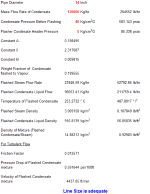
1. Amount of condensate flashed is calculated.
2. Further to above the density of the mixture (condensate+flashed steam) is found out.
3. Using two pressure drop correlations, pressure per 100 ft. is calculated.
4. Also, the velocity of the mixture in the line of specified size is calculated. If the velocity is lower than 5000 Foot/Min., the specified line size is said to be adequate.
Calculation Reference
Fluid mechanics
Condensate Line
Chemical Plant Design
Sizing condensate lines is important for ensuring proper condensate drainage and preventing issues such as water hammer, excessive noise, or inadequate condensate removal. Condensate lines are typically used in steam systems to transport the condensed steam (condensate) back to a condensate receiver or boiler feedwater system.
To size a condensate line, follow these steps:
-
Determine the condensate load: Calculate the amount of condensate generated by the system, usually expressed in kilograms per hour (kg/h) or pounds per hour (lb/h). This can be based on the steam consumption of the equipment, heat exchanger capacities, or other system requirements.
-
Choose an appropriate condensate line velocity: Select a suitable velocity for the condensate flow in the pipe, typically between 1 to 3 meters per second (3.3 to 9.8 feet per second). Higher velocities can increase the risk of water hammer or pipe erosion, while lower velocities can cause inadequate condensate drainage.
-
Calculate the required condensate line flow area: Divide the condensate load by the chosen velocity and the density of the condensate (approximately 1000 kg/m³ or 62.43 lb/ft³ for water at room temperature).
Flow Area = Condensate Load / (Velocity * Density)
where:
- Flow Area = cross-sectional area of the condensate line in square meters (m²) or square feet (ft²)
- Condensate Load = condensate flow rate in kg/h or lb/h
- Velocity = chosen condensate line velocity in m/s or ft/s
- Density = density of the condensate in kg/m³ or lb/ft³
- Determine the pipe diameter: Calculate the inside diameter of the pipe by using the following formula:
Diameter = 2 * ?(Flow Area / ?)
where:
- Diameter = inside diameter of the condensate line in meters (m) or feet (ft)
- Flow Area = cross-sectional area of the condensate line in m² or ft²
- ? = pi (approximately 3.14159)
- Select the appropriate pipe size: Choose a commercially available pipe size with an inside diameter equal to or greater than the calculated diameter. Account for any fittings, valves, and other components that may affect the condensate flow.
Keep in mind that these calculations provide a general guideline for sizing condensate lines. Actual system requirements may vary based on factors such as pipe material, operating pressure, temperature, and installation conditions. Always consult relevant codes, standards, and manufacturer guidelines when designing and sizing condensate lines.
Calculation Preview
Full download access to any calculation is available to users with a paid or awarded subscription (XLC Pro).
Subscriptions are free to contributors to the site, alternatively they can be purchased.
Click here for information on subscriptions.


