PWB Trace Current Sizing

Description
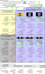
Printed Wiring Board Trace, Vias and Spoke sizes are evaluated for current carrying capacity. Conservatively based on MIL-HNBK-251 fusing equation and compared to IPC-D-275 amperage guidelines, this spreadsheet fills in the missing dimension for trace sizing: LENGTH!
Calculation Reference
PWB Trace Current Sizing
Electric Circuits
Electricity
Printed Wiring Boards (PWBs) have traces, vias, and spokes that serve as conductive pathways for current to flow between electronic components. The current carrying capacity, or ampacity, of these elements is an important factor to consider when designing a PWB. It ensures that the board operates safely and efficiently without overheating or causing damage to the components.
MIL-HNBK-251 (Military Handbook) provides conservative guidelines for determining the current carrying capacity of traces, vias, and spokes on a PWB. Following these guidelines can help ensure the reliability and safety of the board under various operating conditions.
-
Trace current carrying capacity: The current carrying capacity of a trace depends on its width, thickness, and the temperature rise above ambient temperature that is considered acceptable. Wider and thicker traces can handle higher current levels. The MIL-HNBK-251 provides tables and charts that relate trace width and thickness to the allowable current for a given temperature rise.
-
Vias current carrying capacity: Vias are small holes in the PWB that electrically connect traces on different layers. The current carrying capacity of a via depends on its diameter, barrel length (thickness), and the plating material (usually copper). The handbook provides guidelines on calculating via current capacity based on these parameters.
-
Spoke current carrying capacity: Spokes are small conductive pathways that connect PWB pads to their surrounding copper planes. The current carrying capacity of a spoke depends on its width, thickness, and the acceptable temperature rise. Similar to traces, the handbook provides tables and charts to estimate the current capacity of spokes based on their dimensions.
In summary, MIL-HNBK-251 offers conservative guidelines for determining the current carrying capacity of traces, vias, and spokes on a Printed Wiring Board. By following these guidelines, designers can ensure that the PWB can safely handle the current levels required by the electronic components and minimize the risk of overheating or damage. Note that these guidelines are conservative and may not always represent the most optimal design choices for every application. In some cases, industry standards such as IPC-2152 can provide more accurate and up-to-date information for PWB design.
Calculation Preview
Full download access to any calculation is available to users with a paid or awarded subscription (XLC Pro).
Subscriptions are free to contributors to the site, alternatively they can be purchased.
Click here for information on subscriptions.


